
Today we are starting to discuss first of three options to connect on-premise to Aviatrix Transit. This architecture allows you to use existing IPSec and BGP capable networking device to connect to Aviatrix Transit. I’ve listed brief steps and constrains highlighted
- Create ExpressRoute (ER) Circuit
- Configure Azure Private BGP Peering from the ER Circuit to On-Premise device
- Deploy Aviatrix Transit vNet and Transit Gateways
- Create GatewaySubnet for ExpressRoute Gateway (ERGW) in Aviatrix Transit vNet and deploy Express Route Gateway
- Create ER Connection between the ER circuit and ERGW
- Validate BGP route propagated to Aviatrix Transit Gateway eth0 subnet route table and connectivity. This connectivity will act as underlay
- Create BGP over IPSec tunnels from on-premise device towards Aviatrix Transit Gateways as overlay to exchange on-premise routes with cloud routes
- Each IPSec tunnel have 1.25G throughput limit
- Azure only support IPSec, not GRE as tunneling protocol
- Maximum number of IPv4 routes advertised from Azure private peering from the VNet address space for an ExpressRoute connection is 1000. But since we are using BGP over IPSec overlay, we can bypass this limit.
Create Express Route Circuit
According to definition in ExpressRoute circuits and peering
- An ExpressRoute circuit represents a logical connection between your on-premises infrastructure and Microsoft cloud services through a connectivity provider.
- A circuit is uniquely identified by a standard GUID called as a service key (s-key).
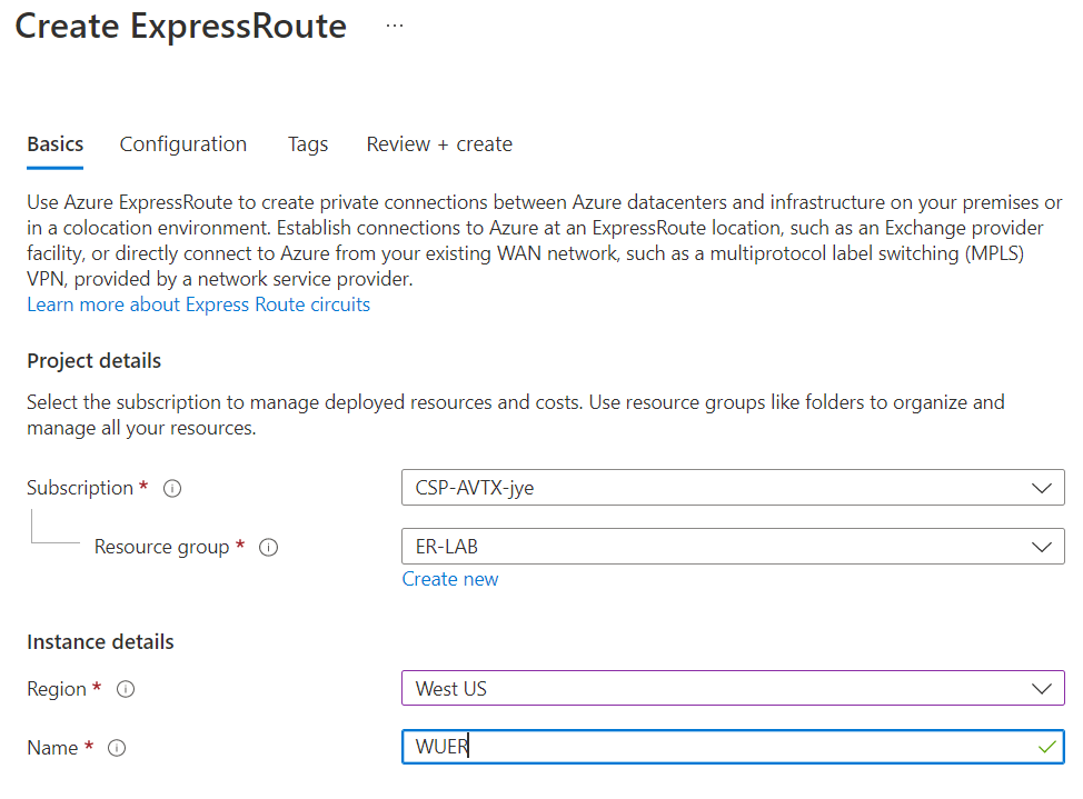
Create a Resource Group, preferred in the same region as the Express Route Circuit.
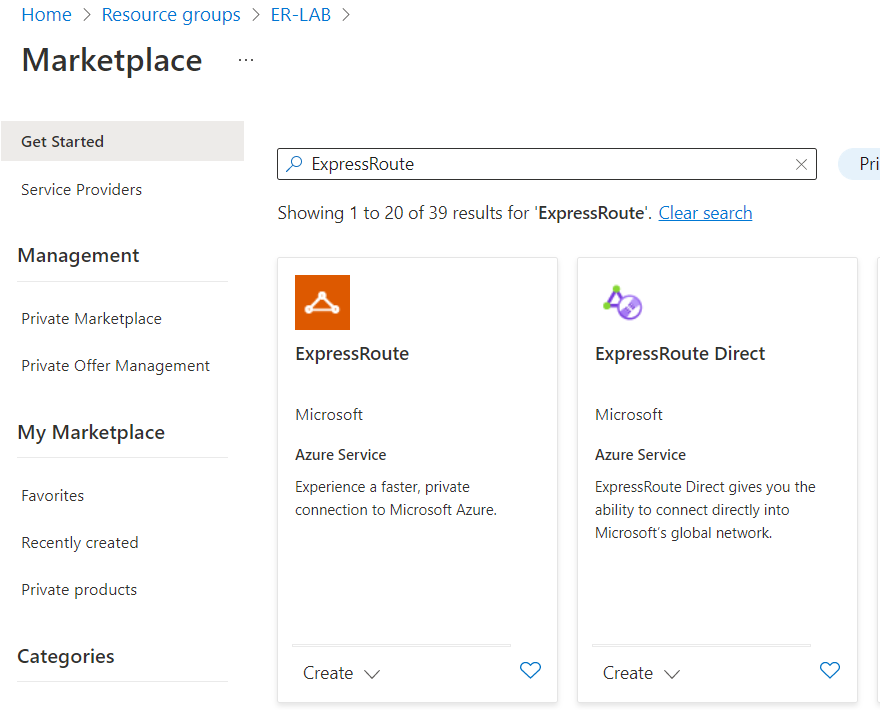
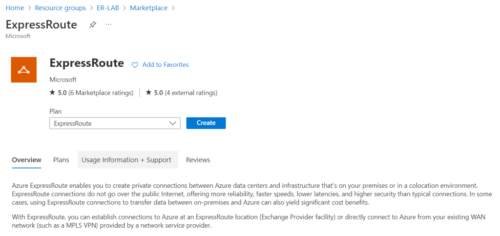
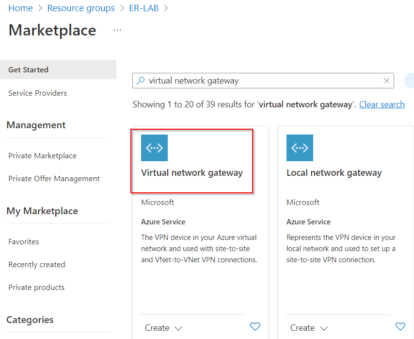
Within the Resource Group, create a new resource, search in Marketplace -> ExpressRoute
In my lab, I’m using ExpressRoute, not ExpressRoute Direct (Which is a direct peering with Microsoft of 10Gbps or 100Gbps)
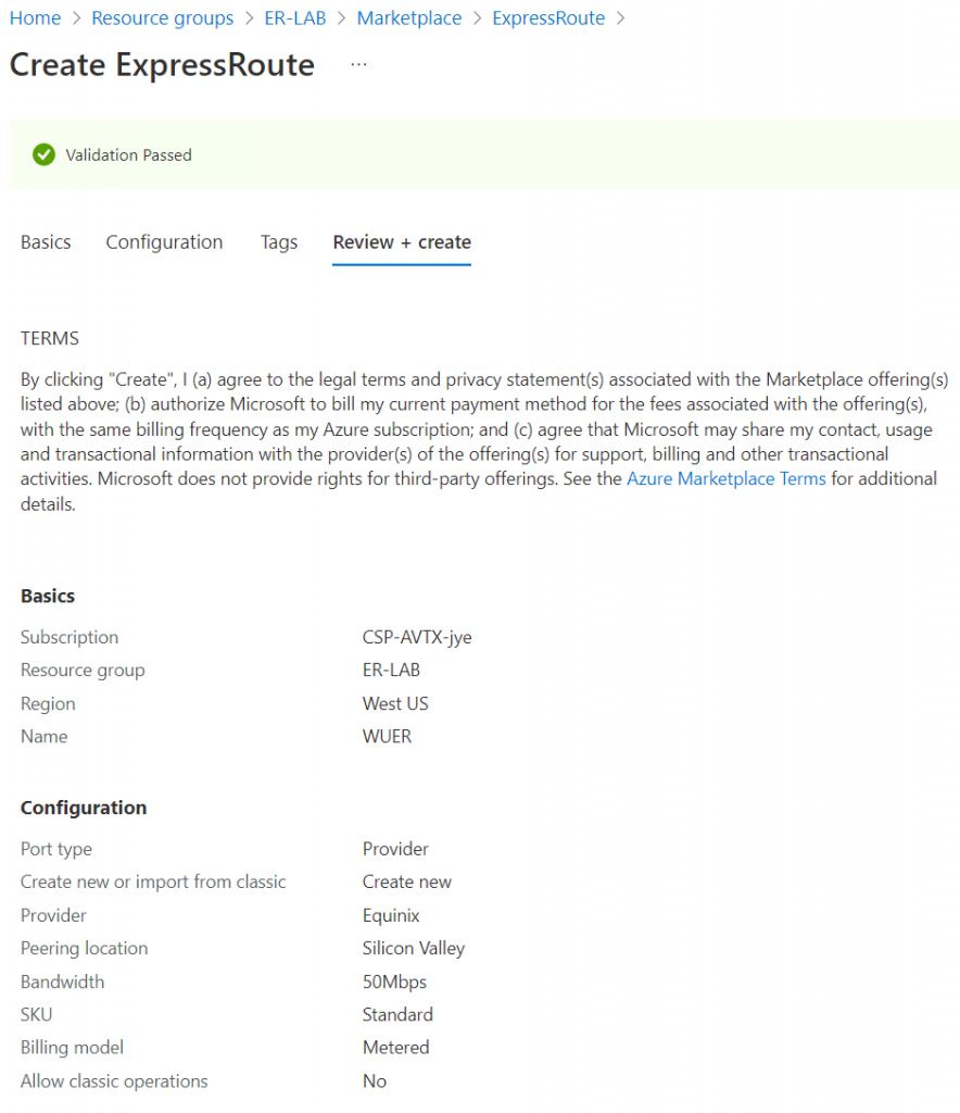
Select the resource group created earlier, and confirm region, and give your Express Route a Name
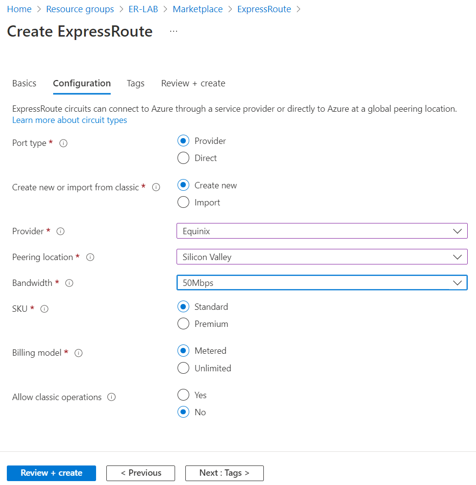
- Select Provider if it’s not Direct Peering with Microsoft.
- Select Peering location
- Select Bandwidth, SKU and Billing Model
Review and create
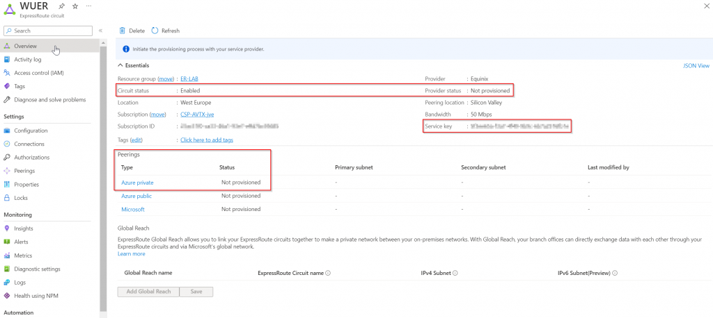
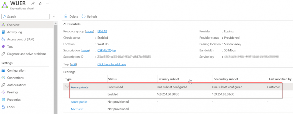
The circuit is created and shows as enabled. Provider status should show as Not provisioned. You need to take the Service Key and to the service provider for the circuit to be provisioned. Also note that the Azure Private isn’t been provisioned as well.
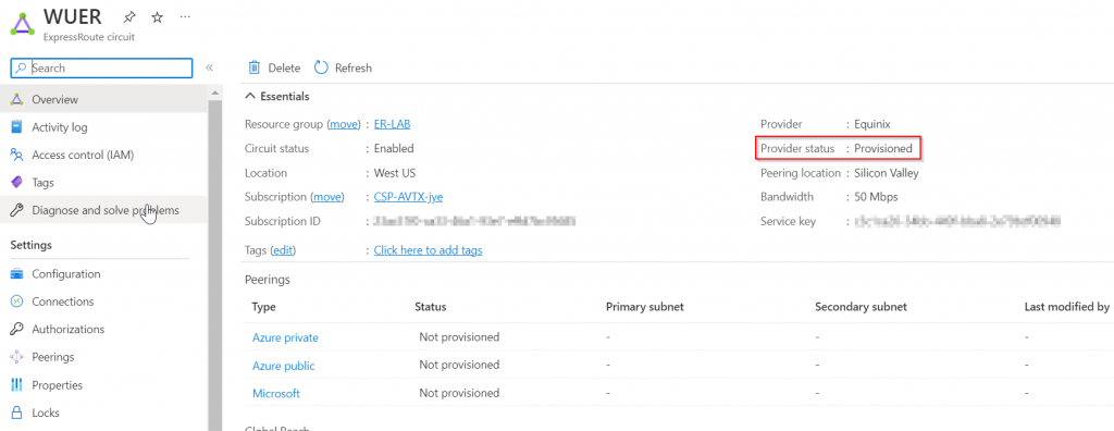
After provider side completed their setup, the circuit should show as Provisioned.
Configure Azure Private Peering
There are three type of peering possible via Express Route:
- Azure Private Peering: Connectivity to Private Virtual Network, where IaaS and PaaS are deployed. This is where we will be focusing on.
- Microsoft Peering Connectivity to Microsoft online services (Microsoft 365 and Azure PaaS services with public IPs)
- Azure Public Peering: (deprecated for new circuits, use Microsoft Peering instead)
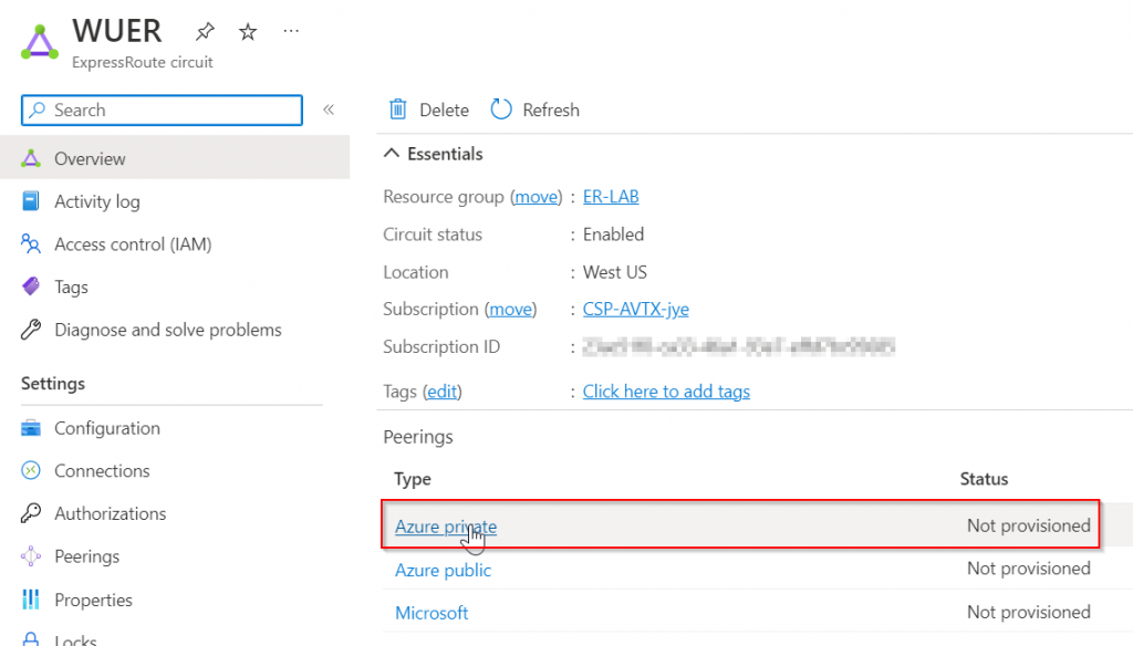
The newly created circuit need to establish BGP peering with your on-premise device for the private connectivity. Reference article: Azure private peering
In my lab environment, the point to point connectivity has already been setup, and we don’t have secondary link, or backup circuit.
interface GigabitEthernet0/0/0.803
 description to be connected to an Azure ER circuit
 encapsulation dot1Q 803
interface GigabitEthernet0/0/0.813
 description to be connected to an Azure ER backup circuit
 encapsulation dot1Q 813
Start to configure Azure private peering in Azure Portal:
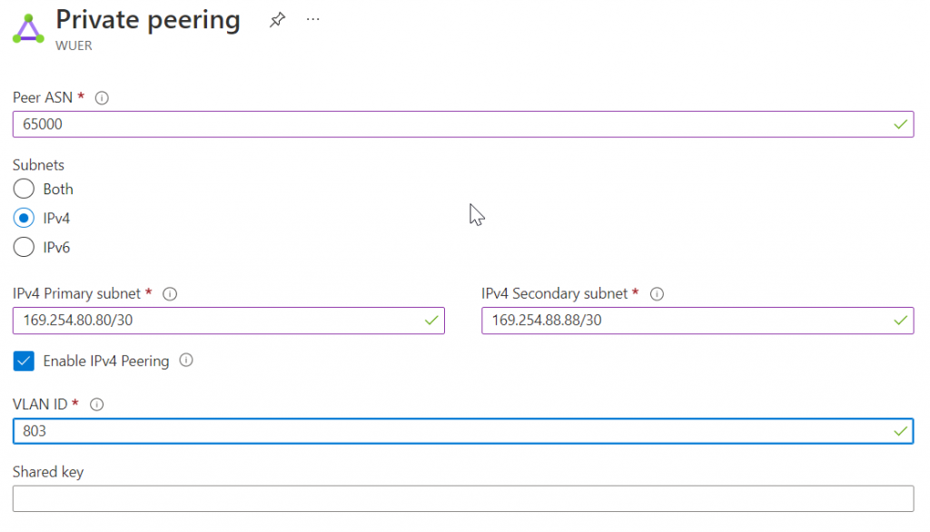
Azure Private Peering have two physical ports, each port/link need to be assigning unique /30 subnets. Also both ports belong to the same VLAN. To have full redundancy, you need two routers on-premise connect to both ports. In this lab, I’ve only got a single router, so only the primary subnet will be used. Credit to Jorge Cortes for the clarification!
Enter ASN from on-premise device, and setup two /30 subnet.
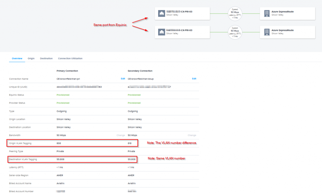
NOTE: It appears that Equinix perform VLAN translating from Azure side two ports with the same VLAN ID, to Equinix side one port with two VLAN IDs. Following example showed a different circuit, with two ports in Azure Side with VLAN ID 55.808, but translated to Equinix side with one port with two VLAN IDs: 808 and 818. Credit to Piotr Bednarski for clarification!
The private peering has been provisioned
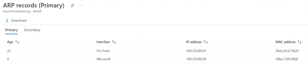
For the primary subnet, 169.254.80.80/30, first usable IP address need to be assigned to on-premise router (in this case 169.254.80.81) , as Microsoft uses the second usable IP for its router (in this case 169.254.80.82).
Configure BGP on the on-premise router
ISR-3#conf t
Enter configuration commands, one per line.  End with CNTL/Z.
ISR-3(config)#interface GigabitEthernet0/0/0.803
ISR-3(config-subif)#
ISR-3(config-subif)#ip address 169.254.80.81 255.255.255.252
ISR-3(config-subif)#end
Test connectivity
ISR-3#ping 169.254.80.82 source 169.254.80.81
Type escape sequence to abort.
Sending 5, 100-byte ICMP Echos to 169.254.80.82, timeout is 2 seconds:
Packet sent with a source address of 169.254.80.81
!!!!!
Success rate is 100 percent (5/5), round-trip min/avg/max = 1/1/2 ms
Now configure BGP from on-premise router side, Microsoft uses AS 12076 for Azure public, Azure private and Microsoft peering.
ISR-3#conf t
Enter configuration commands, one per line.  End with CNTL/Z.
ISR-3(config)#router bgp 65000
ISR-3(config-router)#neighbor 169.254.80.82 remote-as 12076
ISR-3(config-router)#neighbor 169.254.80.82 description Express Route
ISR-3(config-router)#address-family ipv4
ISR-3(config-router-af)#neighbor 169.254.80.82 activate
ISR-3(config-router-af)#neighbor 169.254.80.82 soft-reconfiguration inbound
Check to validate BGP session is up
ISR-3#show ip bgp summary
BGP router identifier 192.168.77.1, local AS number 65000
BGP table version is 18, main routing table version 18
5 network entries using 1240 bytes of memory
5 path entries using 680 bytes of memory
1/1 BGP path/bestpath attribute entries using 280 bytes of memory
0 BGP route-map cache entries using 0 bytes of memory
0 BGP filter-list cache entries using 0 bytes of memory
BGP using 2200 total bytes of memory
BGP activity 9/4 prefixes, 9/4 paths, scan interval 60 secs

Neighbor        V           AS MsgRcvd MsgSent   TblVer  InQ OutQ Up/Down  State/PfxRcd
169.254.80.82   4        12076      11      11       18    0    0 00:05:31        0
Config a loopback adapter
ISR-3#conf t
Enter configuration commands, one per line.  End with CNTL/Z.
ISR-3(config)#interface Loopback77
ISR-3(config-if)#ip address 192.168.77.1 255.255.255.255
ISR-3(config-if)#end
Advertise the loopback adapter
ISR-3#conf t
Enter configuration commands, one per line.  End with CNTL/Z.
ISR-3(config)#router bgp 65000
ISR-3(config-router)#address-family ipv4
ISR-3(config-router-af)#network 192.168.77.1 mask 255.255.255.255
ISR-3(config-router-af)#end
Validation from Azure Portal
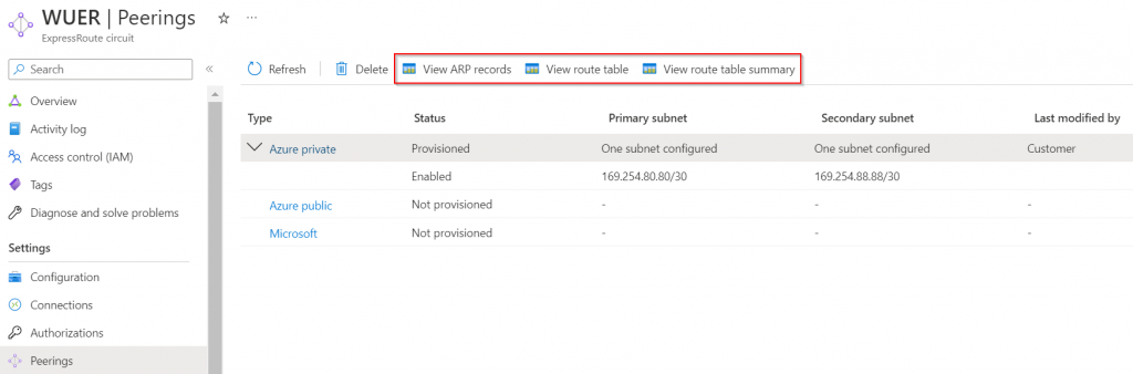
View ARP records -> this validates L2 connectivity
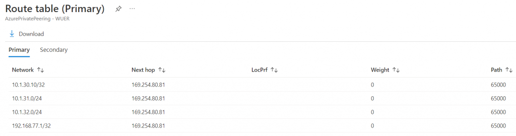
View route table -> Since my on-premise router already have BGP network advertisement configured, the advertised networks are listed, including the loopback address.
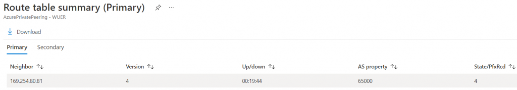
View route table summary -> Show how long the BGP session is up and version it received
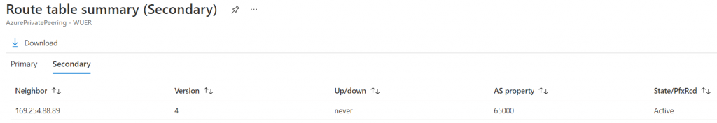
We don’t have secondary link, so the secondary BGP status shows never.
Create Aviatrix Transit
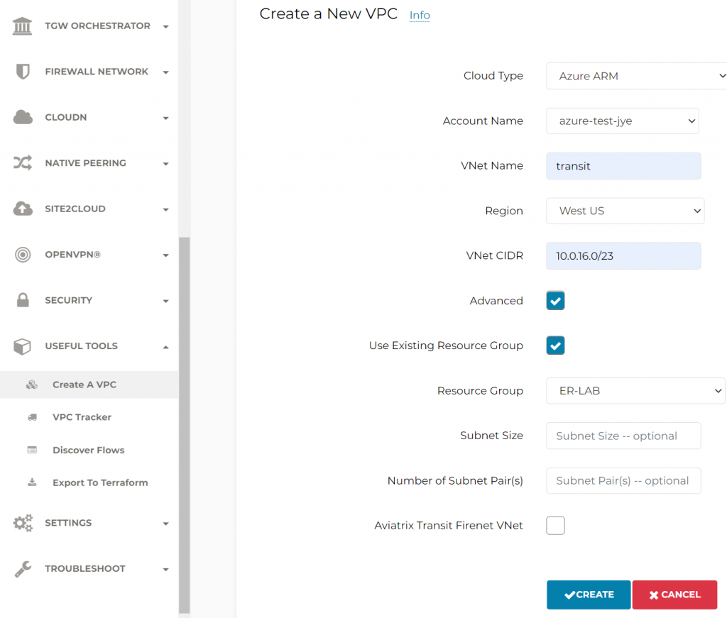
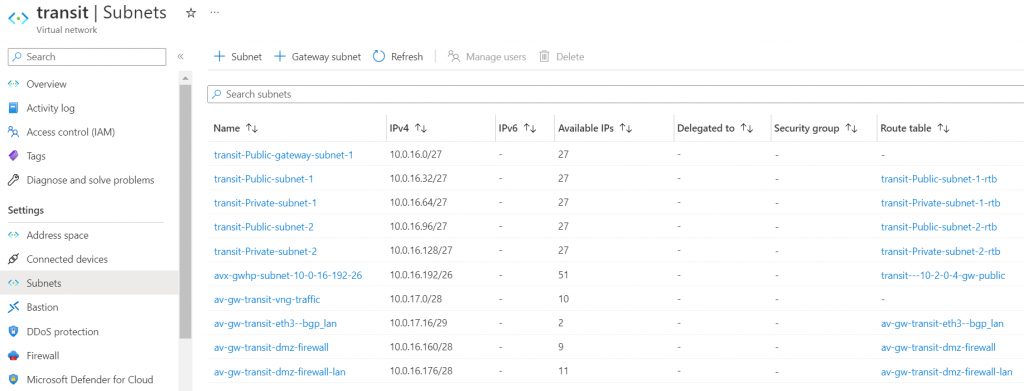
Create vNet for Aviatrix Transit, use Advanced function to select existing Resource Group
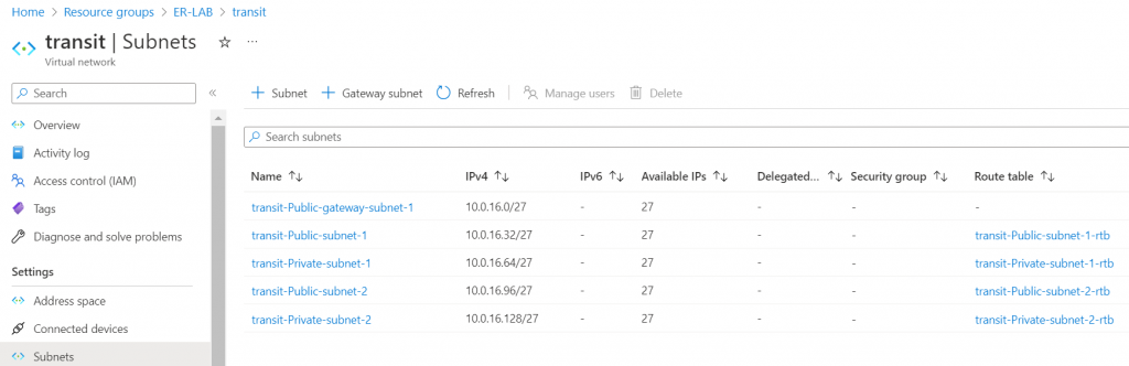
These subnets and route tables are been created
Create Transit Gateway and enable the features need to be enable, as otherwise the Transit Gateway need to be deleted and recreated to enable insane mode or BGP over LAN.
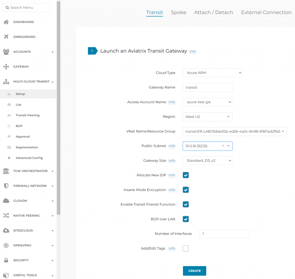
It is recommended to deploy transit gateways into two separate Availability Zones (AZ), this example is in West US region, it doesn’t have Availability Zones. Also note since we have Insane Mode Encryption selected, it will need /26 subnet for each transit gateway, which will support up to 50 secondary IPs for IPSec tunnels.
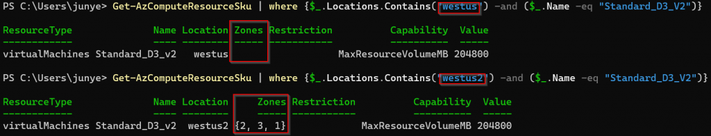
Note: You can use PowerShell command to check AZ availability in certain region. For example, Standard_D3_V2 is available in 3 AZs in West US 2, but not available in West US.
Aviatrix Controller manages the creation of additional subnet and route tables, note the difference:
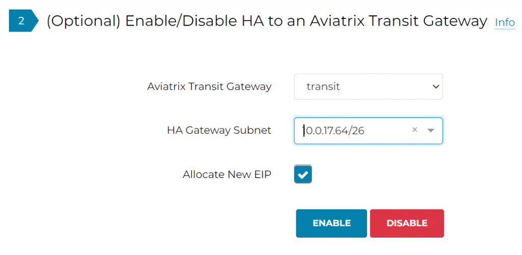
Enable HA Transit Gateway in a different subnet, note 10.0.17.64/26 subnet doesn’t exist yet, Aviatrix Controller automatically allocate the next available /26 range for HA gateway.
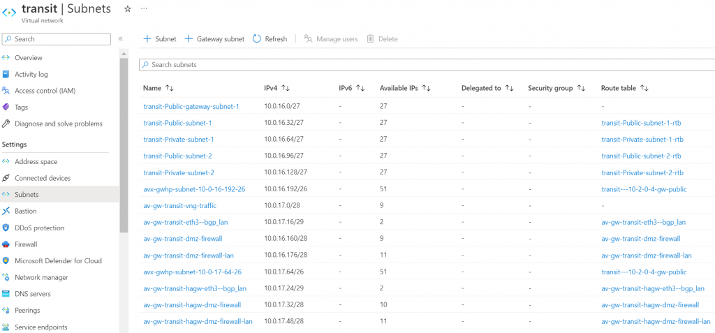
After HA gateway creation completed, if you switch back to Azure, you will notice additional subnet and route tables created for HA gateway to communicate with Firewall/BGP over LAN, and intra-gateway communications.
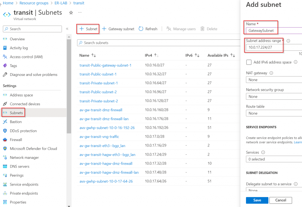
Deploy ExpressRoute Gateway (ERGW)
In this blog, we are deploying ERGW in the same Aviatrix Transit vNet. ERGW require /27 subnet called “GatewaySubnet” to be created. This blog we are using 10.0.16.0/23 CIDR range, and we will be using the last /27 range will be 10.0.17.224/27
Alternative design:
- Create a separate vNet, and create /27 “GatewaySubnet” subnet
- Deploy ERGW in this subnet
- Create vNet peering from Aviatrix Transit vNet to ERGW vNet, and check “Use remote gateway”
- Create vNet peering from ERGW vNet to Aviatrix Transit vNet, and check “Allow gateway transit”
- Pro: No disturbance of Aviatrix Transit vNet
- Con: Additional vNet peering charge
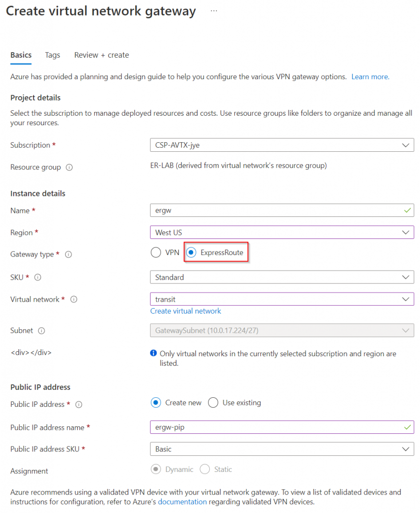
Create ERGW, which is one of the Virtual network gateway (the other type is VPN Gateway)
Make sure to select region, ExpressRoute gateway type. Then select Aviatrix Transit vNet, and create new public IP:
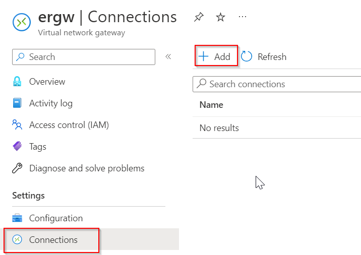
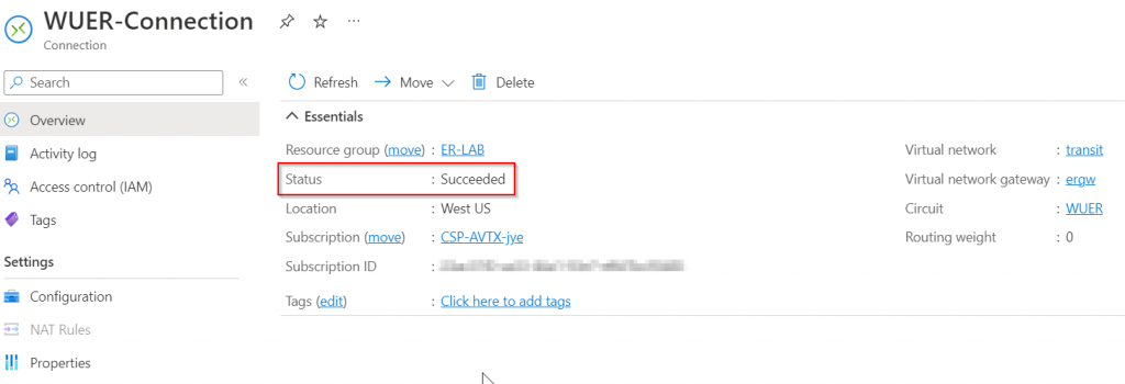
After the ERGW is created. Create a connection towards the express route circuit
Select ExpressRoute as Connection type, then selected the ExpressRoute Circuit
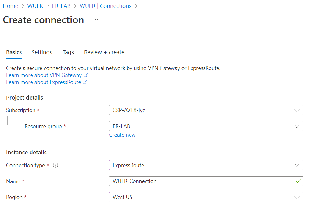
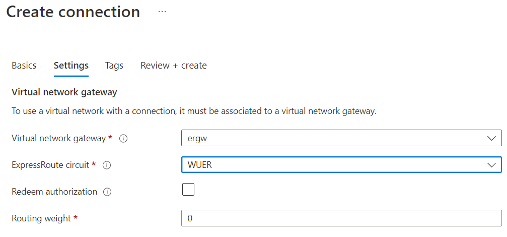
If the Azure Private Peering BGP session is up and running, the connection status should be Succeeded.
Validate and fine tune underlay connectivity
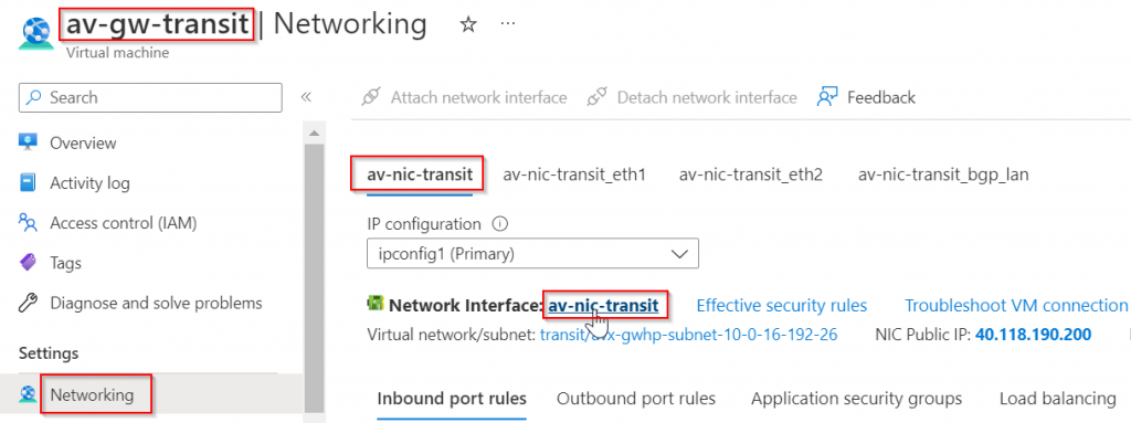
Go to the primary Aviatrix Transit Gateway deployed earlier in Azure Portal, networking -> Select first NIC (eth0). Note down:
- Subnet it belongs to: avx-gwhp-subnet-10-0-16-192-26 in this example (subnet name will be different if Insane mode isn’t enabled)
- Private IP address: 10.0.16.196 in this example
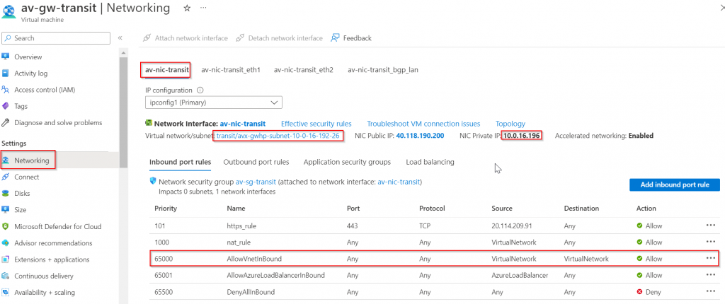
Also noticed Network Security Group default rule priority 65000, AllowVnetInBound, allows everything from VirtualNetwork tag to VirtualNetwork tag. According to: Virtual network service tags, VirtualNetwork definition:
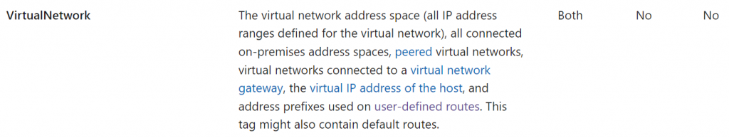
This means on-premise device should be able to reach the Aviatrix Transit Gateway (In AWS, you need to specify on-premise address range in Security Group of the incoming connection)
Let’s check on the route table on the subnet, and make sure it does have propagate gateway route enabled.
In the Aviatrix Transit vNet -> Subnet -> Search the subnet noted, and click on the Route Table it’s associated
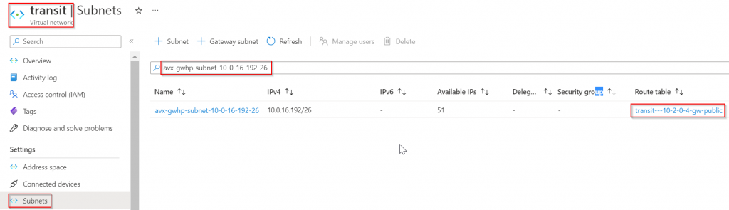
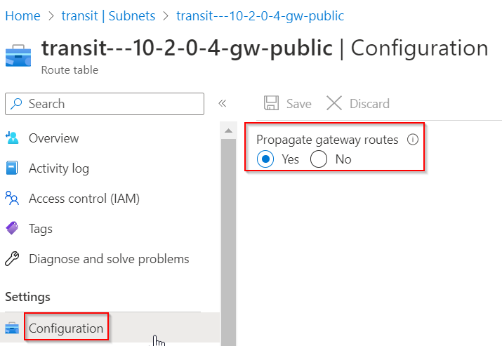
In the route table -> configuration -> Confirm Propagate gateway routes is enabled (this should be the default)
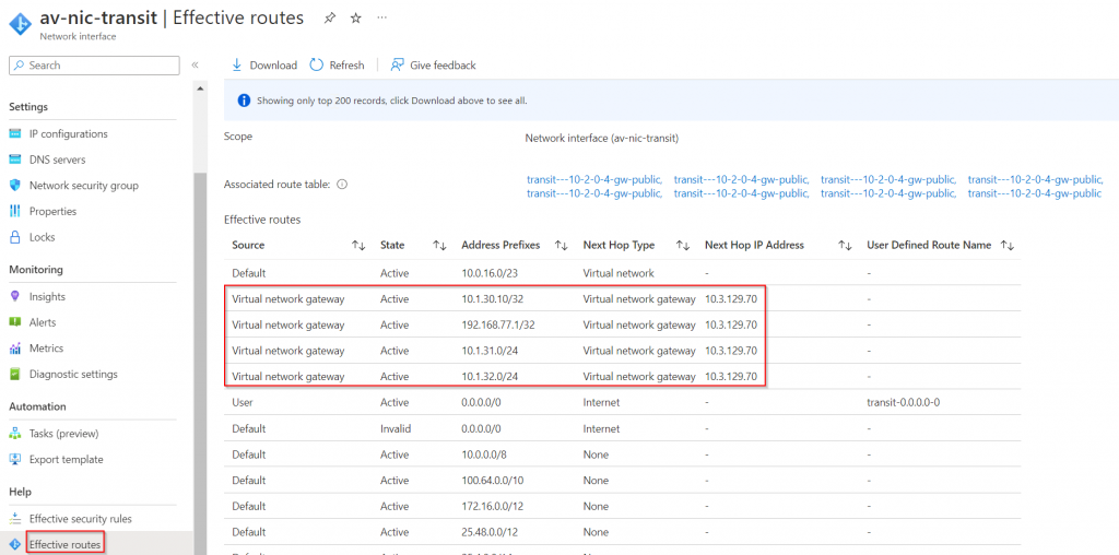
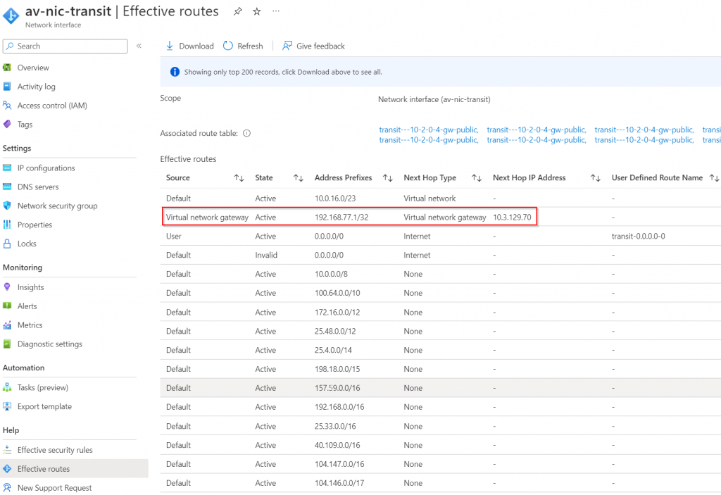
Now goes back to the Aviatrix Transit Gateway, make sure it’s up and running, click on eth0 interface, then run effective route
Notice the routes we have observed earlier in Express Route Circuit -> Peerings -> Azure private -> View route table, are all listed here as Virtual network gateway type of routes, and next hop IP 10.3.129.70 is Microsoft Enterprise Edge (MSEE) Routers.
From on-premise confirm connectivity to the Aviatrix Transit Gateway
ISR-3#ping 10.0.16.196 source 192.168.77.1
Type escape sequence to abort.
Sending 5, 100-byte ICMP Echos to 10.0.16.196, timeout is 2 seconds:
Packet sent with a source address of 192.168.77.1
!!!!!
Success rate is 100 percent (5/5), round-trip min/avg/max = 2/2/3 ms
From Aviatrix Transit Gateway, confirm connectivity to on-premise
On on-premise router, advertise only loopback via the BGP connection towards ER, as the connectivity between Loopback and Aviatrix Transit Gateways will be treated as underlay, and we will be building BGP over IPSec tunnels on top of this underlay
ISR-3#conf t
Enter configuration commands, one per line.  End with CNTL/Z.
ISR-3(config)#ip prefix-list router-to-er description Advertise Loopback only
ISR-3(config)#ip prefix-list router-to-er seq 10 permit 192.168.77.1/32
ISR-3(config)#router bgp 65000
ISR-3(config-router)#address-family ipv4
ISR-3(config-router-af)#neighbor 169.254.80.82 prefix-list router-to-er out
ISR-3(config-router-af)#end
Check effective route on Aviatrix Transit Gateway eth0 again, we should see it can only see the loopback.
Create BGP over IPSec overlay.
As of now, the Aviatrix Transit Gateway subnet route table has received route from on-premise router via ERGW VNG. But the Aviatrix Transit Gateway itself hasn’t learned on-premise route yet.
You can observe Aviatrix Transit Gateway Route table via Controller -> Multi-Cloud Transit -> List -> Transit -> Select Transit Gateway -> Details/Diag
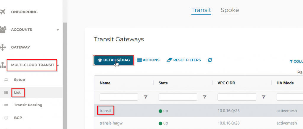
Find the Gateway Routing Table section, then click on Refresh button:
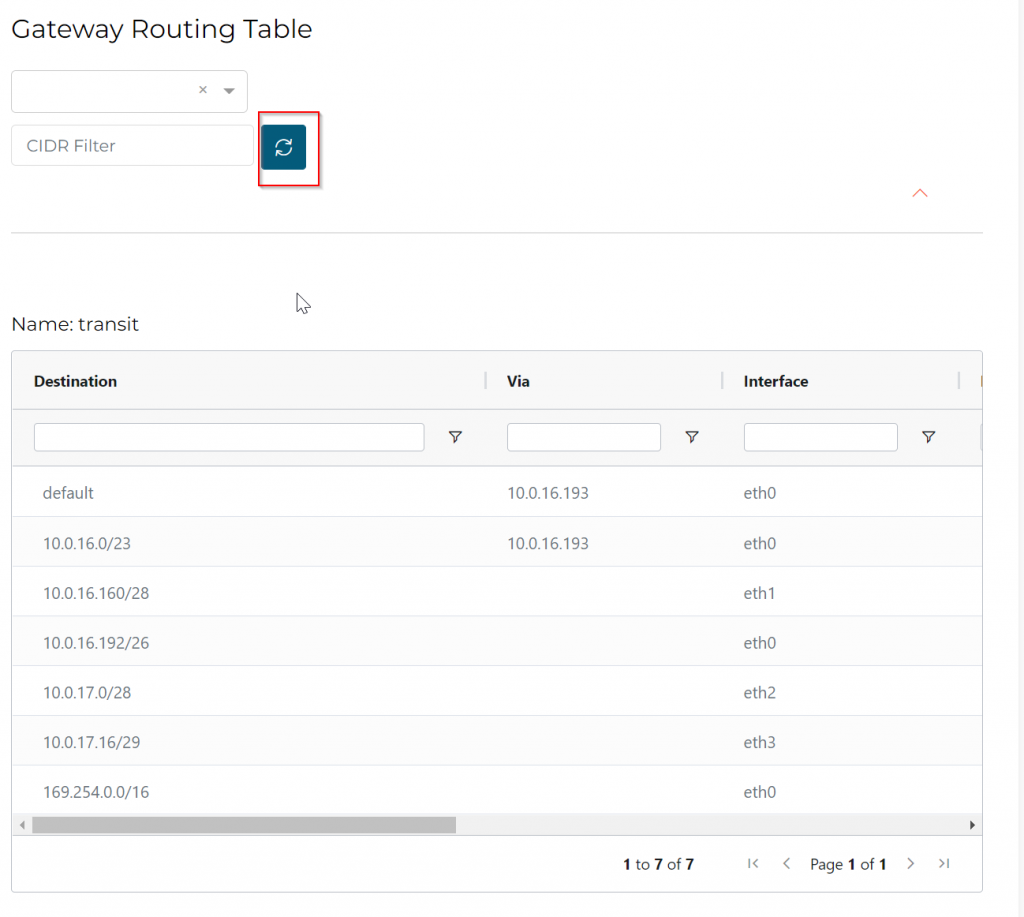
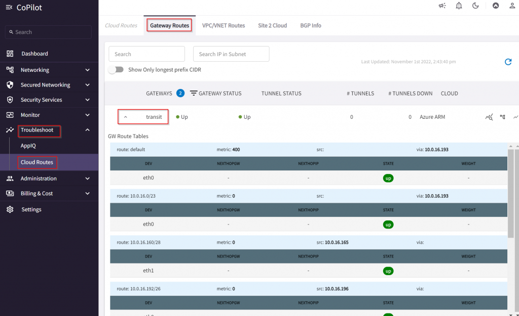
Or goes to CoPilot -> Troubleshoot -> Cloud Routes -> Gateway Routes, select the Transit Gateway
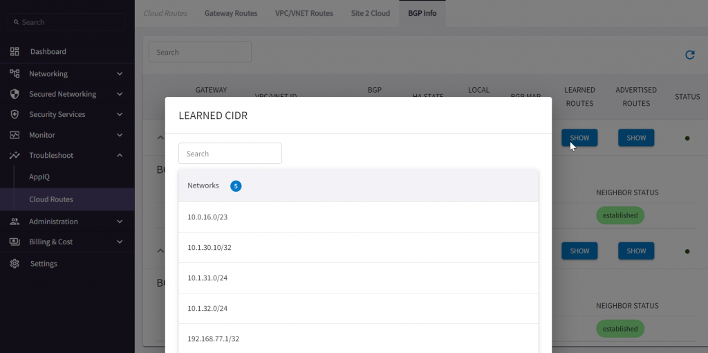
As you may recall in the screenshot of Express Route Circuit -> Peerings -> Azure Private -> View route table, we were receiving following CIDRs:
10.1.30.10/32
10.1.31.0/24
10.1.32.0/24
192.168.77.1
They are not in the Aviatrix Transit Gateway route table. Let’s build the BGP over IPSec tunnel between the on-premise router towards Aviatrix Transit Gateways.
To understand how tunnels will be build via this workflow, visit my blog: Aviatrix Site to Cloud Connection demystified
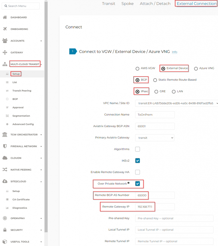
Multi-Cloud Transit -> Setup -> External Connection -> External Devices
- Aviatrix Gateway BGP ASN : Enter ASN for Aviatrix Transit Gateway here. Or if you already set it up in Multi-Cloud Transit -> Advanced Config -> Local AS Number, it will be prefilled here.
- Enable Remote Gateway HA
- Over Private Network : Checked
- Remote BGP AS Number: 65000
- Remote Gateway IP: 192.168.77.1 (Loopback)
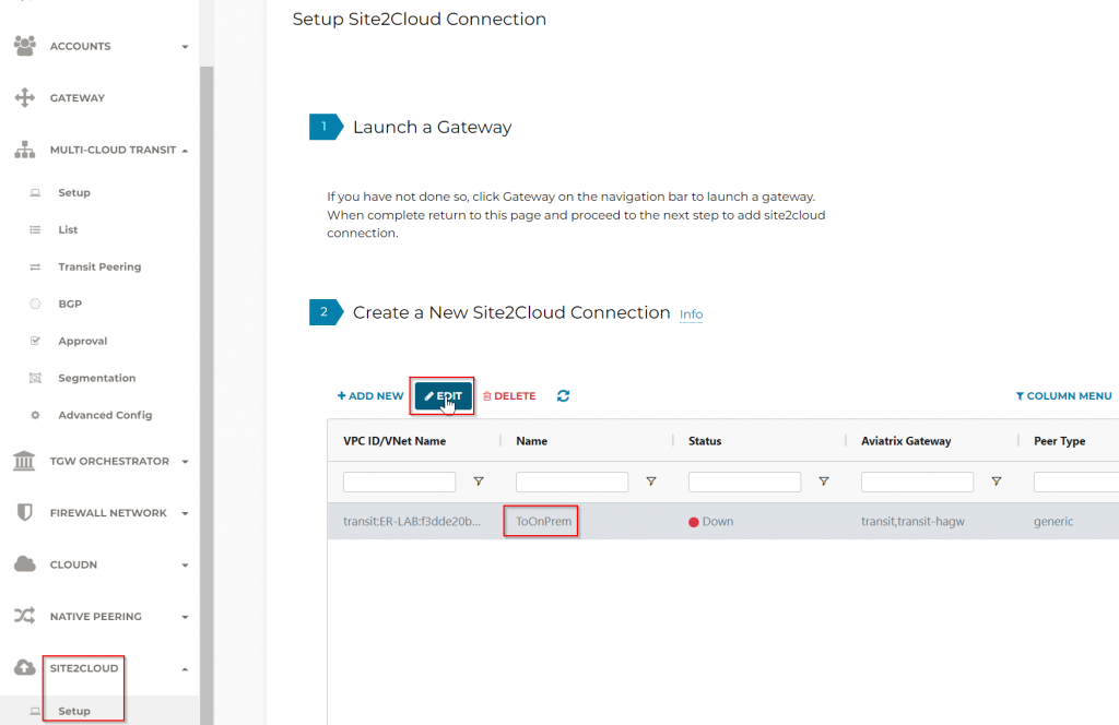
After the External connection from Transit Gateway has been created, head to Site2Cloud -> Setup -> Select the connection showed up here, then click on Edit button
Here you can generate configuration file based on target system. Since I’m using Cisco ISR, I will select corresponding Vendor, Platform, Software and click on Download Configuration
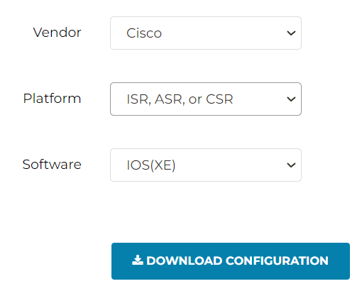
Generated config file attached
Replace <crypto_policy_number> with 1
Replace <tunnel_number1> with 11
Replace <tunnel_number2> with 12
Replace <ios_wan_interface1> with loopback ip: 192.168.77.1
Replace <ios_wan_interface2> with loopback ip: 192.168.77.1
Paste the config into ISR conf t window
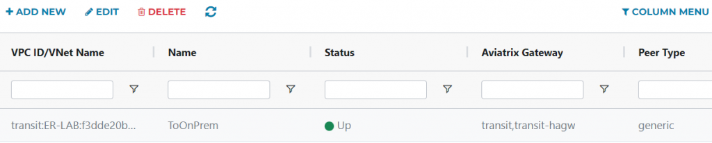
Validate IPSec tunnel is up
Wait a few min, head back to Aviatrix Controller -> Site2Cloud -> Setup -> Refresh. You should see the Site2Cloud connection is Up
If you run into issue, goes to Site2Cloud -> Diagnostics to troubleshoot
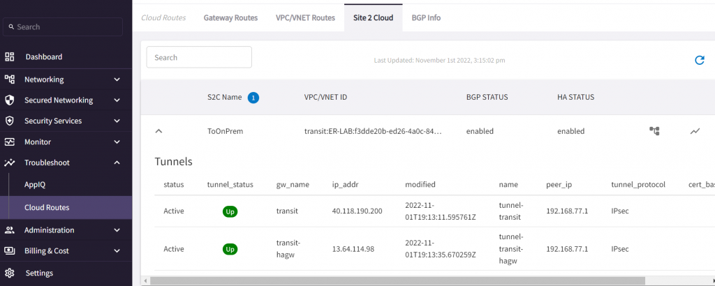
In a few min, CoPilot -> Troubleshoot -> Cloud Routes -> Site 2 Cloud also should have Site2Cloud connection shows up
validate BGP is up
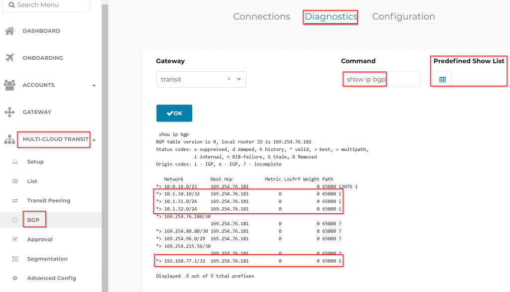
Controller -> Multi-Cloud Transit -> BGP -> Diagnostics -> Predefined Show List -> show ip bgp
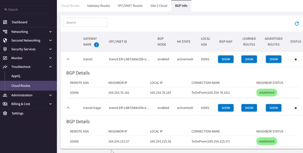
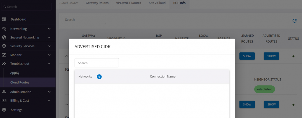
CoPilot -> Troubleshoot -> Cloud Routes -> BGP Info
Learned CIDR from on-premise
Advertised CIDR should be empty right now, as there’s no spoke attached to the Aviatrix Transit
To Test CIDR advertise back on-prem
- Either we can create a new spoke and attach to transit, it will be advertised to on-premise
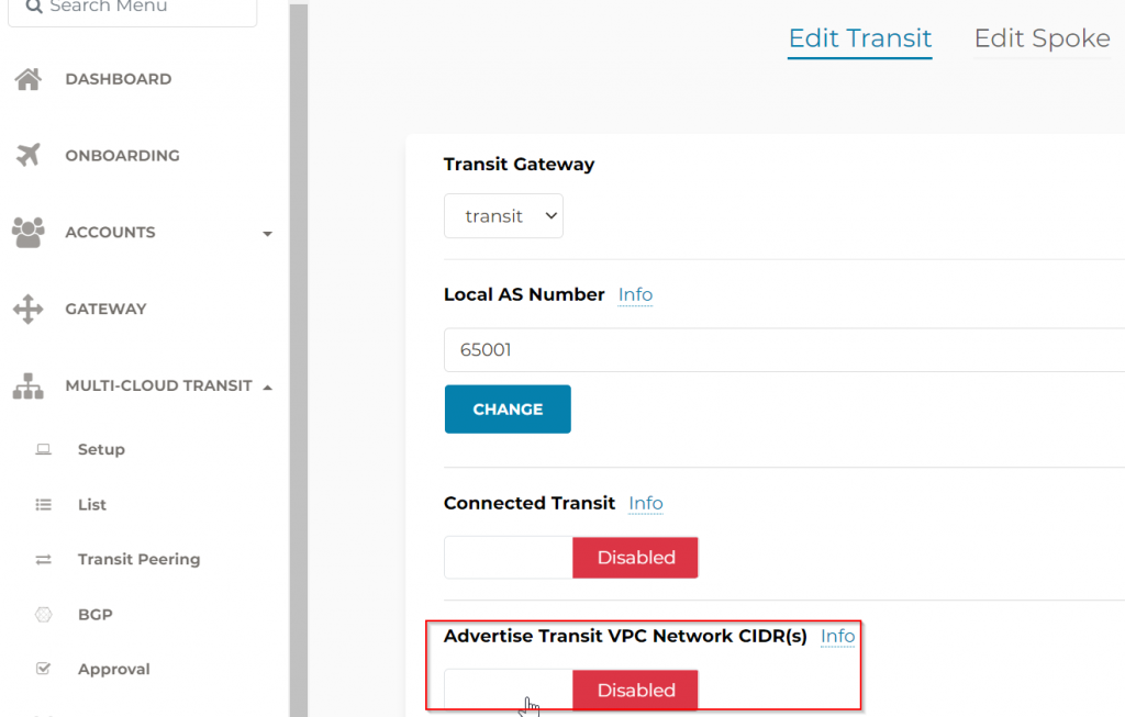
- Or we can follow Multi-Cloud Transit -> Advanced Config -> enable Advertise Transit VPC Network CIDR(s) (This is used for situation when there are workload running within Transit VPC, normally we don’t encourage this)
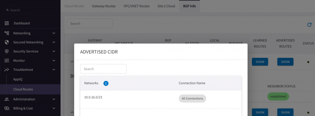
After this, if we go back to CoPilot, we can see Transit VPC CIDR get advertised.
Check on the on-premise router side, note 10.0.16.0/23 got received from both ERGW and Aviatrix Transit, The route received from AS 12076 has a right arrow > beside it indicate it’s the best route. You may consider VRF to segment these two BGP routes, and apply filters so the route learned via underlay won’t propagated further down to on-premise.
ISR-3#show ip bgp
BGP table version is 25, local router ID is 192.168.77.1
Status codes: s suppressed, d damped, h history, * valid, > best, i - internal,
              r RIB-failure, S Stale, m multipath, b backup-path, f RT-Filter,
              x best-external, a additional-path, c RIB-compressed,
              t secondary path, L long-lived-stale,
Origin codes: i - IGP, e - EGP, ? - incomplete
RPKI validation codes: V valid, I invalid, N Not found

     Network          Next Hop            Metric LocPrf Weight Path
 *    10.0.16.0/23     169.254.215.58           0             0 65001 i
 *                     169.254.76.182           0             0 65001 i
 *>                    169.254.80.82                          0 12076 i
 *>   10.1.30.10/32    0.0.0.0                  0         32768 i
 *>   10.1.31.0/24     0.0.0.0                  0         32768 i
 *>   10.1.32.0/24     0.0.0.0                  0         32768 i
 *>   169.254.76.180/30
                      0.0.0.0                  0         32768 ?
 *>   169.254.80.80/30 0.0.0.0                  0         32768 ?
 *>   169.254.96.0/29  0.0.0.0                  0         32768 ?
 *>   169.254.215.56/30
                      0.0.0.0                  0         32768 ?
 *>   192.168.77.1/32  0.0.0.0                  0         32768 i
Once this test is done. remember to disable Advertise Transit VPC Network CIDR(s)
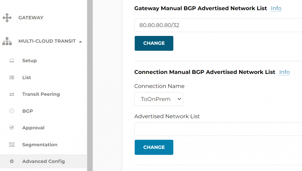
- Or we can use Multi-Cloud Transit -> Advanced Config -> Gateway Manual BGP Advertised Network List. This setting changes ALL BGP advertised CIDR from Aviatrix Transit Gateway towards all connections
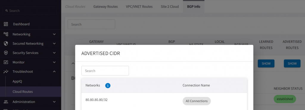
ISR-3#show ip bgp
BGP table version is 27, local router ID is 192.168.77.1
Status codes: s suppressed, d damped, h history, * valid, > best, i - internal,
              r RIB-failure, S Stale, m multipath, b backup-path, f RT-Filter,
              x best-external, a additional-path, c RIB-compressed,
              t secondary path, L long-lived-stale,
Origin codes: i - IGP, e - EGP, ? - incomplete
RPKI validation codes: V valid, I invalid, N Not found

     Network          Next Hop            Metric LocPrf Weight Path
 *>   10.0.16.0/23     169.254.80.82                          0 12076 i
 *>   10.1.30.10/32    0.0.0.0                  0         32768 i
 *>   10.1.31.0/24     0.0.0.0                  0         32768 i
 *>   10.1.32.0/24     0.0.0.0                  0         32768 i
 *m   80.80.80.80/32   169.254.215.58           0             0 65001 i
 *>                    169.254.76.182           0             0 65001 i
 *>   169.254.76.180/30
                      0.0.0.0                  0         32768 ?
 *>   169.254.80.80/30 0.0.0.0                  0         32768 ?
 *>   169.254.96.0/29  0.0.0.0                  0         32768 ?
 *>   169.254.215.56/30
                      0.0.0.0                  0         32768 ?
 *>   192.168.77.1/32  0.0.0.0                  0         32768 i
- Or we can use Multi-Cloud Transit -> Advanced Config -> Connection Manual BGP Advertised Network List. This setting will only affect specified Connection
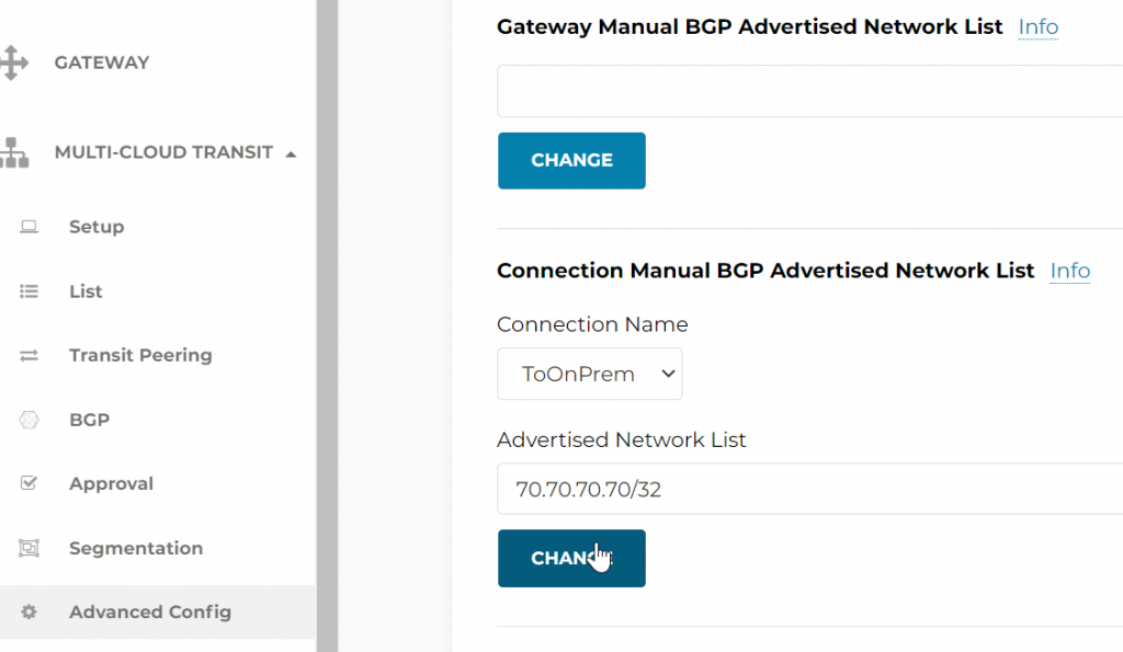
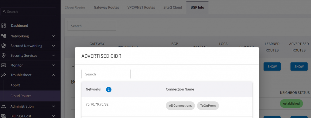
ISR-3#show ip bgp
BGP table version is 31, local router ID is 192.168.77.1
Status codes: s suppressed, d damped, h history, * valid, > best, i - internal,
              r RIB-failure, S Stale, m multipath, b backup-path, f RT-Filter,
              x best-external, a additional-path, c RIB-compressed,
              t secondary path, L long-lived-stale,
Origin codes: i - IGP, e - EGP, ? - incomplete
RPKI validation codes: V valid, I invalid, N Not found

     Network          Next Hop            Metric LocPrf Weight Path
 *>   10.0.16.0/23     169.254.80.82                          0 12076 i
 *>   10.1.30.10/32    0.0.0.0                  0         32768 i
 *>   10.1.31.0/24     0.0.0.0                  0         32768 i
 *>   10.1.32.0/24     0.0.0.0                  0         32768 i
 *m   70.70.70.70/32   169.254.215.58           0             0 65001 i
 *>                    169.254.76.182           0             0 65001 i
 *>   169.254.76.180/30
                      0.0.0.0                  0         32768 ?
 *>   169.254.80.80/30 0.0.0.0                  0         32768 ?
 *>   169.254.96.0/29  0.0.0.0                  0         32768 ?
 *>   169.254.215.56/30
                      0.0.0.0                  0         32768 ?
 *>   192.168.77.1/32  0.0.0.0                  0         32768 i