Scenario: One of our customers are primary in Azure, after merger and acquisitions, them acquired hundreds of AWS accounts, where workloads are deployed to default VPCs, which all have this address space: 172.31.0.0/16
They are looking for a solution to provide bi-directional private connectivity to these workloads in AWS from Azure without overhead of route management, also provide visibility to the traffic.
Here below is the proposed solution:
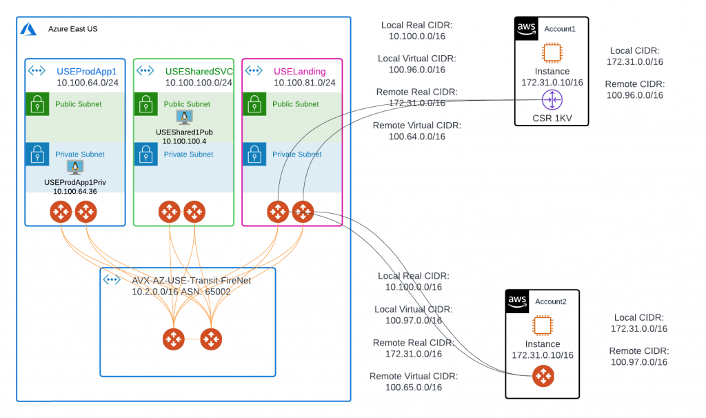
In above diagram, Azure workloads are deployed in spoke vNets, these spoke vNets are attached to hub Transit FireNet and are fully routable.
USEProdApp1Priv is deployed in private subnet.
USEShared1Pub have an EIP that we can SSH to.
Azure side have a summarized real CIDR of 10.100.0.0/16
AWS side top right corner, account1, we would use a Cisco CSR 1000
AWS bottom right corner, account2, we would use a standalone Aviatrix Gateway
Let’s take a look at the differences between Cisco CSR and Aviatrix Gateway
Part 1 – Cisco CSR 1000 to Aviatrix Spoke GW mapped NAT configuration
Testing environment:
Aviatrix Controller: 6.6.5545
Aviatrix Gateways: 6.6.5545
Cisco CSR 1000: 16.09.08
Since bi-directional traffic is needed, in this configuration, IPs have one to one mapping.
Azure side real CIDR: 10.100.0.0/16, we will use 100.96.0.0/16 for it’s virtual CIDR.
AWS side will use virtual IP: 100.96.64.36, when tries to reach Azure side real IP: 10.100.64.36
Traffic flow from AWS side to Azure side, note NAT happens on Landing Spoke Gateway. (SIP = Source IP, DIP = Destination IP)
| AWS Client / CSR | Landing Spoke GW | Transit GW | Prod Spoke GW | Azure Client | |
| SIP | 172.31.0.10 | 100.64.0.10 | 100.64.0.10 | 100.64.0.10 | 100.64.0.10 |
| DIP | 100.96.64.36 | 10.100.64.36 | 10.100.64.36 | 10.100.64.36 | 10.100.64.36 |
AWS side real CIDR: 172.31.0.0/16, we will use 100.64.0.0/16 for it’s virtual CIDR.
Azure side will use virtual IP: 100.64.0.10, when tries to reach AWS side real IP: 172.31.0.10
Traffic flow from Azure side to AWS side, note NAT happens on Landing Spoke Gateway. (SIP = Source IP, DIP = Destination IP)
| Azure Client | Prod Spoke GW | Transit GW | Landing Spoke GW | CSR / AWS Client | |
| SIP | 10.100.64.36 | 10.100.64.36 | 10.100.64.36 | 10.100.64.36 | 100.96.64.36 |
| DIP | 100.64.0.10 | 100.64.0.10 | 100.64.0.10 | 100.64.0.10 | 172.31.0.10 |
Launch CSR
In this test, selected: Cisco Cloud Services Router (CSR) 1000V – BYOL for Maximum Performance, you may need to subscribe to the market place image
Default c5.large
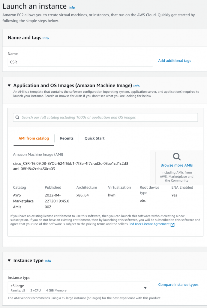
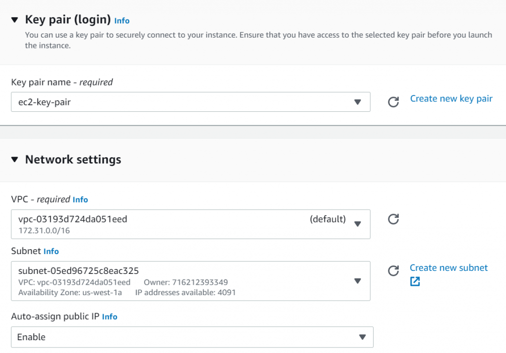
Select your key pair and select the default VPC and a public subnet. Will need to obtain an EIP later for production workload
Obtain public IPs of Aviatrix Spoke Gateways in Landing vNet, CSR need to establish IPSec connections to these two public IPs
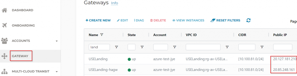
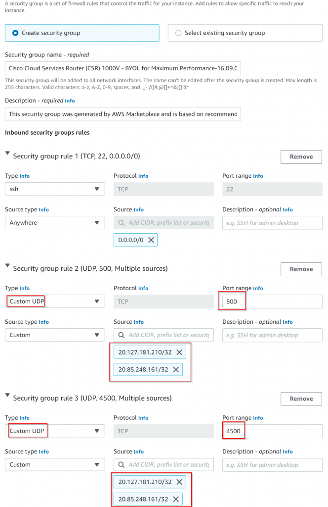
As such, need to modify CSR security group to allow UDP 500 and UDP 4500 from these two public IPs:
Launch instance
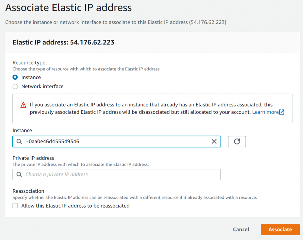
Allocate EIP, then associate the EIP with CSR
Test connect to CSR
ssh -i <your-pem-key> [email protected] -oKexAlgorithms=+diffie-hellman-group14-sha1Create Site to Cloud connection using Mapped NAT in Aviatrix Controller
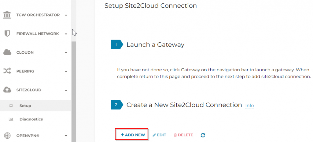
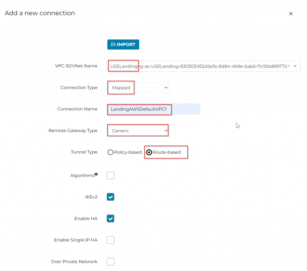
Goes to Aviatrix controller web page, SITE2CLOUD -> Setup -> 2 Create a New Site2CloudConnection -> ADD NEW
VPC ID/VNet Name : Select Landing vNet
Connection Type: Mapped
Connection Name: This is the name used for Aviatrix to track the Site2Cloud connection
Remote Gateway Type: Generic
Tunnel Type: Route Based
IKEv2: Enabled by default
Enable HA: Checked as we do have two gateways deployed for HA
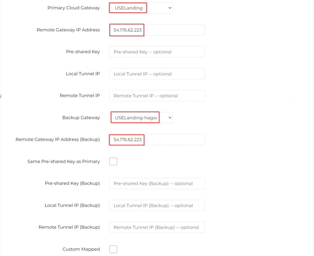
Primary Cloud Gateway: Select Primary Aviatrix Landing GW
Remote Gateway IP address: Enter CSR’s public IP
Backup Gateway: Select HA Aviatrix Landing GW
Remote Gateway IP Address (Backup): Enter CSR’s public IP
Remote Subnet (Real): 172.31.0.0/16
Remote Subnet (Virtual): 100.64.0.0/16
Local Subnet (Real): 10.100.0.0/16
Local Subnet (Virtual): 100.96.0.0/16
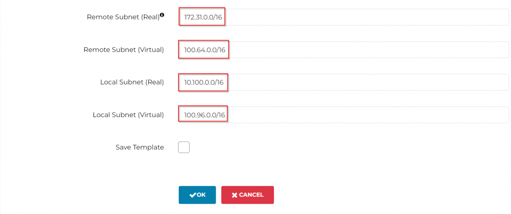
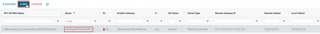
Click OK to create the Site2Cloud connection
CONFIGURE CSR
Select the newly created Site2Cloud connection, and click on Edit button
Under Connection Detail:
Vendor: Cisco
Platform: IS, ASR, or CSR
Software: IOS(XE)
Click on DOWNLOAD CONFIGURATION
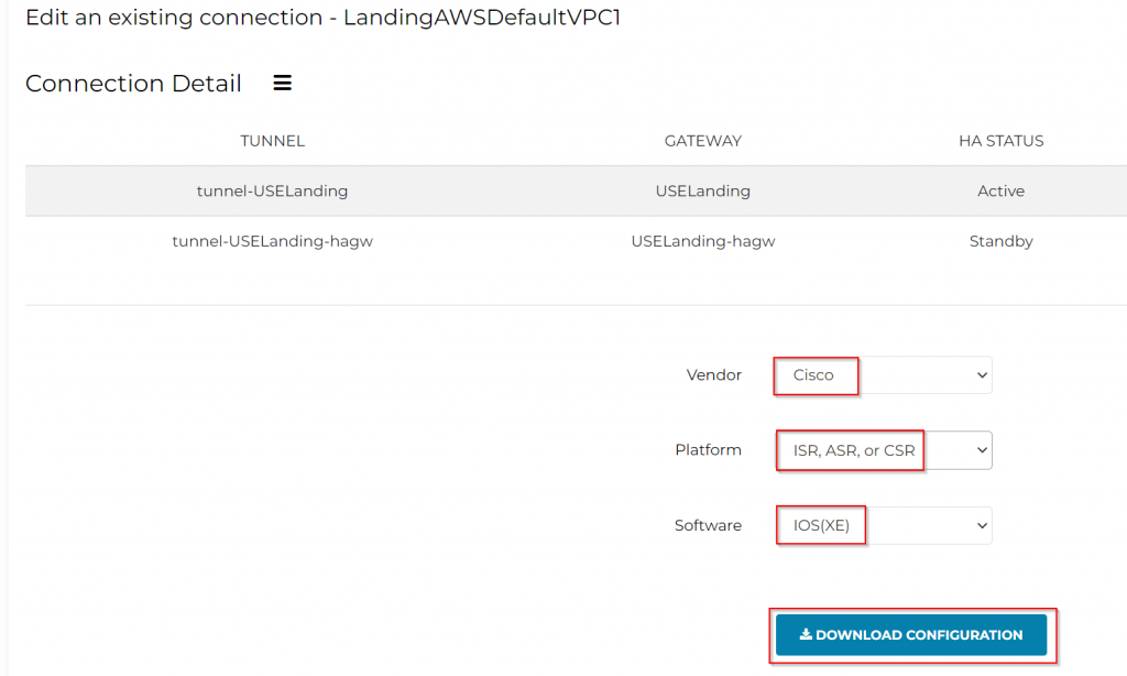
This will create a text file for configuring your CSR
Sample content of the file, I’ve highlighted sections need to be changed, note that although we do have two tunnels, only one can be active due to static route.
! Aviatrix Site2Cloud configuration template
!
! This configuration serves as a general guideline and may have to be modified to
! be functional on your device.
!
! If the provided encryption or authentication type is configured as 'n/a', then
! there was not a known mapping from the selected type to the encryption or
! authentication type expected by the Cisco device.  Please reference the Cisco
! documentation for your device and replace 'n/a' with the expected configuration.
!
! This connection has two IPsec tunnels between the customer gateway and
! Aviatrix gateways in the cloud. Tunnel #1 is the primary tunnel. The
! customer gateway should be configured in such a way that it should
! switch over to tunnel #2 when tunnel #1 fails.
!
! You need to populate these values throughout the config based on your setup:
! <crypto_policy_number>: the IKE crypto policy number
! <tunnel_number1>: the primary IPSec tunnel interface number
! <tunnel_number2>: the backup IPSec tunnel interface number
! <ios_wan_interface1>: the primary source interface of tunnel packets
! <ios_wan_interface2>: the backup source interface of tunnel packets
! <customer_tunnel_ip1>: any un-used IPv4 address for the primary tunnel interface
!                        when static routing is used (e.g. 1.1.1.1)
! <customer_tunnel_ip2>: any un-used IPv4 address for the backup tunnel interface
!                        when static routing is used (e.g. 1.1.1.3)
! <netmask>: netmask for customer_tunnel_ip. Please use 255.255.255.255
!
! --------------------------------------------------------------------------------
! IPSec Tunnel #1 (Primary)
! --------------------------------------------------------------------------------
! #1: Internet Key Exchange (IKE) Configuration
! A policy is established for the supported ISAKMP encryption,
! authentication, Diffie-Hellman, lifetime, and key parameters.
!
crypto ikev2 proposal avx-s2c-20.127.181.210
  encryption aes-cbc-256
  integrity sha256
  group 14
  exit
!
crypto ikev2 policy <crypto_policy_number>
  proposal avx-s2c-20.127.181.210
  exit
!
crypto ikev2 keyring 54.176.62.223-20.127.181.210
  peer 54.176.62.223-20.127.181.210
    address 20.127.181.210
    identity address 20.127.181.210
    pre-shared-key P0645IO6UJ8Z8uEf0eXapGxKXlck35L0c124rjFc
    exit
  exit
!
crypto ikev2 profile 54.176.62.223-20.127.181.210
  match identity remote address 20.127.181.210 255.255.255.255
  identity local address 54.176.62.223
  authentication remote pre-share
  authentication local pre-share
  keyring local 54.176.62.223-20.127.181.210
  lifetime 28800
  dpd 10 3 periodic
  exit
!
!---------------------------------------------------------------------------------
! #2: IPSec Configuration
! The IPSec transform set defines the encryption, authentication, and IPSec
! mode parameters.
!
crypto ipsec transform-set 54.176.62.223-20.127.181.210 esp-256-aes esp-sha256-hmac
  mode tunnel
  exit
crypto ipsec df-bit clear
!
crypto ipsec profile 54.176.62.223-20.127.181.210
  set security-association lifetime seconds 3600
  set transform-set 54.176.62.223-20.127.181.210
  set pfs group14
  set ikev2-profile 54.176.62.223-20.127.181.210
  set security-association lifetime kilobytes disable
  set security-association lifetime seconds 3600
  exit
!
!---------------------------------------------------------------------------------------
! #3: Tunnel Interface Configuration
! The virtual tunnel interface is used to communicate with the remote IPSec endpoint
! to establish the IPSec tunnel.
!
interface Tunnel <tunnel_number1>
  ip address 169.254.56.181 255.255.255.252
  ip mtu 1436
  ip tcp adjust-mss 1387
  tunnel source <ios_wan_interface1>
  tunnel mode ipsec ipv4
  tunnel destination 20.127.181.210
  tunnel protection ipsec profile 54.176.62.223-20.127.181.210
  ip virtual-reassembly
  exit
!
!
! --------------------------------------------------------------------------------
! IPSec Tunnel #2 (Backup)
! --------------------------------------------------------------------------------
! #4: Internet Key Exchange (IKE) Configuration
!
crypto ikev2 keyring 54.176.62.223-20.85.248.161
  peer 54.176.62.223-20.85.248.161
    address 20.85.248.161
    identity address 20.85.248.161
    pre-shared-key SyeqOQqT1cvMO2uwR4jHciXSn8Yn3AVYr8CE1dNh
    exit
  exit
!
crypto ikev2 profile 54.176.62.223-20.85.248.161
  match identity remote address 20.85.248.161 255.255.255.255
  identity local address 54.176.62.223
  authentication remote pre-share
  authentication local pre-share
  keyring local 54.176.62.223-20.85.248.161
  lifetime 28800
  dpd 10 3 periodic
  exit
!
!---------------------------------------------------------------------------------
! #5: IPSec Configuration
! The IPSec transform set defines the encryption, authentication, and IPSec
! mode parameters.
!
crypto ipsec transform-set 54.176.62.223-20.85.248.161 esp-256-aes esp-sha256-hmac
  mode tunnel
  exit
!
crypto ipsec profile 54.176.62.223-20.85.248.161
  set security-association lifetime seconds 3600
  set transform-set 54.176.62.223-20.85.248.161
  set pfs group14
  set ikev2-profile 54.176.62.223-20.85.248.161
  set security-association lifetime kilobytes disable
  set security-association lifetime seconds 3600
  exit
!
!---------------------------------------------------------------------------------------
! #6: Tunnel Interface Configuration
! The virtual tunnel interface is used to communicate with the remote IPSec endpoint
! to establish the IPSec tunnel.
!
interface Tunnel <tunnel_number2>
  ip address 169.254.41.117 255.255.255.252
  ip mtu 1436
  ip tcp adjust-mss 1387
  tunnel source <ios_wan_interface2>
  tunnel mode ipsec ipv4
  tunnel destination 20.85.248.161
  tunnel protection ipsec profile 54.176.62.223-20.85.248.161
  ip virtual-reassembly
  exit
!
!---------------------------------------------------------------------------------------
! #7: Routing Configuration
! The static route directs the local traffic to the Aviatrix remote subnets via the tunnel
! interface. When the primary tunnel, Tunnel<tunnel_number1> is down, the <tunnel_number1>
! should be replaced with the backup tunnel, <tunnel_number2>.
!
ip route 100.96.0.0 255.255.0.0 Tunnel<tunnel_number1>
!---------------------------------------------------------------------------------------
!
!
For vendor specific instructions, please go to the following URL:
http://docs.aviatrix.com/#site2cloud
Sample completed configuration:
! Aviatrix Site2Cloud configuration template
!
! This configuration serves as a general guideline and may have to be modified to
! be functional on your device.
!
! If the provided encryption or authentication type is configured as 'n/a', then
! there was not a known mapping from the selected type to the encryption or
! authentication type expected by the Cisco device.  Please reference the Cisco
! documentation for your device and replace 'n/a' with the expected configuration.
!
! This connection has two IPsec tunnels between the customer gateway and
! Aviatrix gateways in the cloud. Tunnel #1 is the primary tunnel. The
! customer gateway should be configured in such a way that it should
! switch over to tunnel #2 when tunnel #1 fails.
!
! You need to populate these values throughout the config based on your setup:
! <crypto_policy_number>: the IKE crypto policy number
! <tunnel_number1>: the primary IPSec tunnel interface number
! <tunnel_number2>: the backup IPSec tunnel interface number
! <ios_wan_interface1>: the primary source interface of tunnel packets
! <ios_wan_interface2>: the backup source interface of tunnel packets
! <customer_tunnel_ip1>: any un-used IPv4 address for the primary tunnel interface
!                        when static routing is used (e.g. 1.1.1.1)
! <customer_tunnel_ip2>: any un-used IPv4 address for the backup tunnel interface
!                        when static routing is used (e.g. 1.1.1.3)
! <netmask>: netmask for customer_tunnel_ip. Please use 255.255.255.255
!
! --------------------------------------------------------------------------------
! IPSec Tunnel #1 (Primary)
! --------------------------------------------------------------------------------
! #1: Internet Key Exchange (IKE) Configuration
! A policy is established for the supported ISAKMP encryption,
! authentication, Diffie-Hellman, lifetime, and key parameters.
!
crypto ikev2 proposal avx-s2c-20.127.181.210
  encryption aes-cbc-256
  integrity sha256
  group 14
  exit
!
crypto ikev2 policy 1
  proposal avx-s2c-20.127.181.210
  exit
!
crypto ikev2 keyring 54.176.62.223-20.127.181.210
  peer 54.176.62.223-20.127.181.210
    address 20.127.181.210
    identity address 20.127.181.210
    pre-shared-key P0645IO6UJ8Z8uEf0eXapGxKXlck35L0c124rjFc
    exit
  exit
!
crypto ikev2 profile 54.176.62.223-20.127.181.210
  match identity remote address 20.127.181.210 255.255.255.255
  identity local address 54.176.62.223
  authentication remote pre-share
  authentication local pre-share
  keyring local 54.176.62.223-20.127.181.210
  lifetime 28800
  dpd 10 3 periodic
  exit
!
!---------------------------------------------------------------------------------
! #2: IPSec Configuration
! The IPSec transform set defines the encryption, authentication, and IPSec
! mode parameters.
!
crypto ipsec transform-set 54.176.62.223-20.127.181.210 esp-256-aes esp-sha256-hmac
  mode tunnel
  exit
crypto ipsec df-bit clear
!
crypto ipsec profile 54.176.62.223-20.127.181.210
  set security-association lifetime seconds 3600
  set transform-set 54.176.62.223-20.127.181.210
  set pfs group14
  set ikev2-profile 54.176.62.223-20.127.181.210
  set security-association lifetime kilobytes disable
  set security-association lifetime seconds 3600
  exit
!
!---------------------------------------------------------------------------------------
! #3: Tunnel Interface Configuration
! The virtual tunnel interface is used to communicate with the remote IPSec endpoint
! to establish the IPSec tunnel.
!
interface Tunnel 1
  ip address 169.254.56.181 255.255.255.252
  ip mtu 1436
  ip tcp adjust-mss 1387
  tunnel source GigabitEthernet1
  tunnel mode ipsec ipv4
  tunnel destination 20.127.181.210
  tunnel protection ipsec profile 54.176.62.223-20.127.181.210
  ip virtual-reassembly
  exit
!
!
! --------------------------------------------------------------------------------
! IPSec Tunnel #2 (Backup)
! --------------------------------------------------------------------------------
! #4: Internet Key Exchange (IKE) Configuration
!
crypto ikev2 keyring 54.176.62.223-20.85.248.161
  peer 54.176.62.223-20.85.248.161
    address 20.85.248.161
    identity address 20.85.248.161
    pre-shared-key SyeqOQqT1cvMO2uwR4jHciXSn8Yn3AVYr8CE1dNh
    exit
  exit
!
crypto ikev2 profile 54.176.62.223-20.85.248.161
  match identity remote address 20.85.248.161 255.255.255.255
  identity local address 54.176.62.223
  authentication remote pre-share
  authentication local pre-share
  keyring local 54.176.62.223-20.85.248.161
  lifetime 28800
  dpd 10 3 periodic
  exit
!
!---------------------------------------------------------------------------------
! #5: IPSec Configuration
! The IPSec transform set defines the encryption, authentication, and IPSec
! mode parameters.
!
crypto ipsec transform-set 54.176.62.223-20.85.248.161 esp-256-aes esp-sha256-hmac
  mode tunnel
  exit
!
crypto ipsec profile 54.176.62.223-20.85.248.161
  set security-association lifetime seconds 3600
  set transform-set 54.176.62.223-20.85.248.161
  set pfs group14
  set ikev2-profile 54.176.62.223-20.85.248.161
  set security-association lifetime kilobytes disable
  set security-association lifetime seconds 3600
  exit
!
!---------------------------------------------------------------------------------------
! #6: Tunnel Interface Configuration
! The virtual tunnel interface is used to communicate with the remote IPSec endpoint
! to establish the IPSec tunnel.
!
interface Tunnel 2
  ip address 169.254.41.117 255.255.255.252
  ip mtu 1436
  ip tcp adjust-mss 1387
  tunnel source GigabitEthernet1
  tunnel mode ipsec ipv4
  tunnel destination 20.85.248.161
  tunnel protection ipsec profile 54.176.62.223-20.85.248.161
  ip virtual-reassembly
  exit
!
!---------------------------------------------------------------------------------------
! #7: Routing Configuration
! The static route directs the local traffic to the Aviatrix remote subnets via the tunnel
! interface. When the primary tunnel, Tunnel<tunnel_number1> is down, the <tunnel_number1>
! should be replaced with the backup tunnel, <tunnel_number2>.
!
ip route 100.96.0.0 255.255.0.0 Tunnel1
!---------------------------------------------------------------------------------------
!
!
For vendor specific instructions, please go to the following URL:
http://docs.aviatrix.com/#site2cloud
Now goes to CSR
conf tThen paste the modified code into CSR console
Switch back to Aviatrix Controller, SITE2CLOUD -> Setup -> Refresh, in a few minutes and you should see the connection status is Green and Up
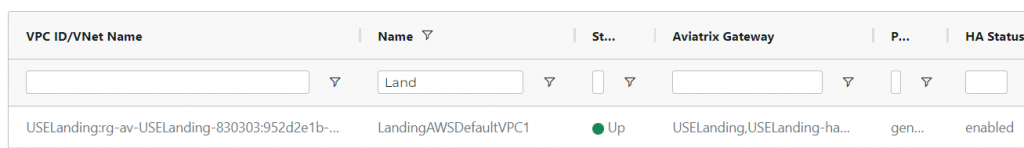
If the connection doesn’t come up in a few minutes, you can go to SITE2CLOUD -> Diagnostics -> Select the connection -> Action: Run analytics or Show Logs
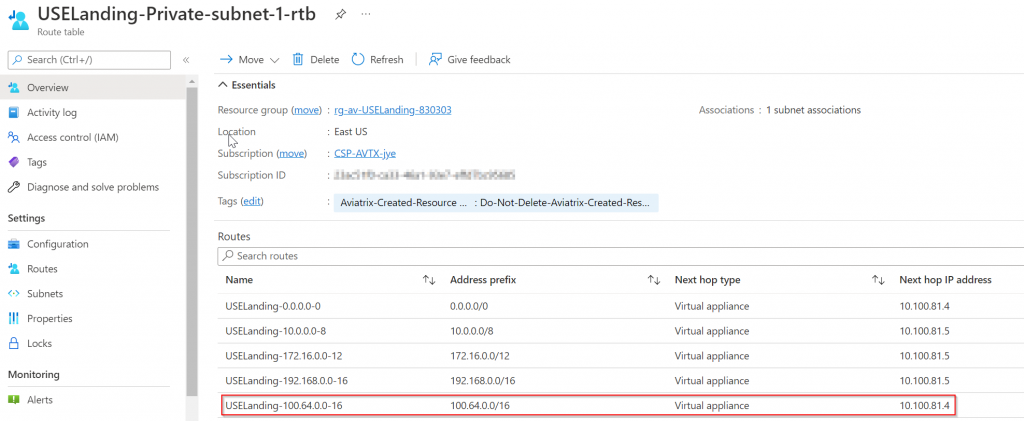
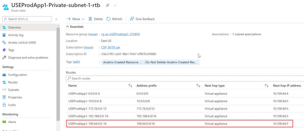
Observe route tables in Azure vNets
It’s worth to note that Aviatrix inject RFC1918 routes into spoke subnets route tables pointing to Aviatrix Spoke Gateways, this steers all traffic towards transit.
In the Landing vNet, since we just created a Site2Cloud connection with static route, Aviatrix controller is aware of this intention and programed AWS virtual CIDR 100.64.0.0/16 point to Aviatrix Spoke Gateway in Landing vNet
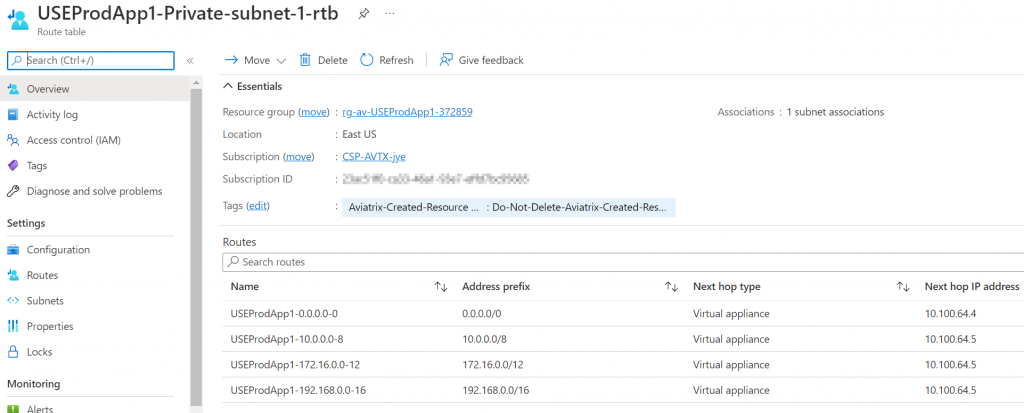
Then how do we get traffic to other connected spoke vNet or even across transits? Note below, Prod spoke vNet only have RFC1918 routes added, and 100.64.0.0/16 is missing:
Allow Site2cloud connection to be accessiable across transit
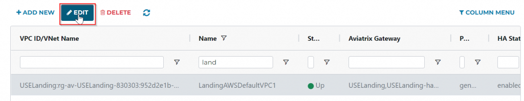
- Select newly created Site2Cloud connection, and click on Edit button:
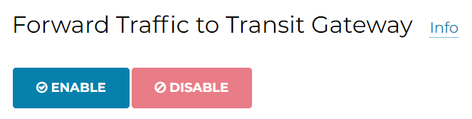
Scroll and Enable Forward Traffic to Transit Gateway
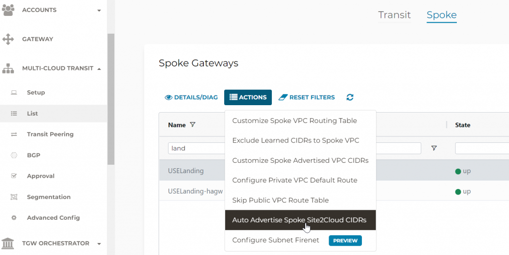
- Aviatrix Controller -> MULTI-CLOUD TRANSIT -> List -> Spoke -> Select primary Landing Gateway -> ACTIONS -> Auto Advertise Spoke Site2Coud CIDRs
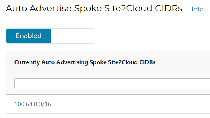
When you click on Enable, you should see 100.64.0.0/16 is been advertised now, since it’s part of landing spoke Site2Cloud CIDRs
Check Prod vNet route table again, and you can see that 100.64.0.0/16 gets added by Aviatrix controller pointing to Prod Spoke Gateway
Test connectivity
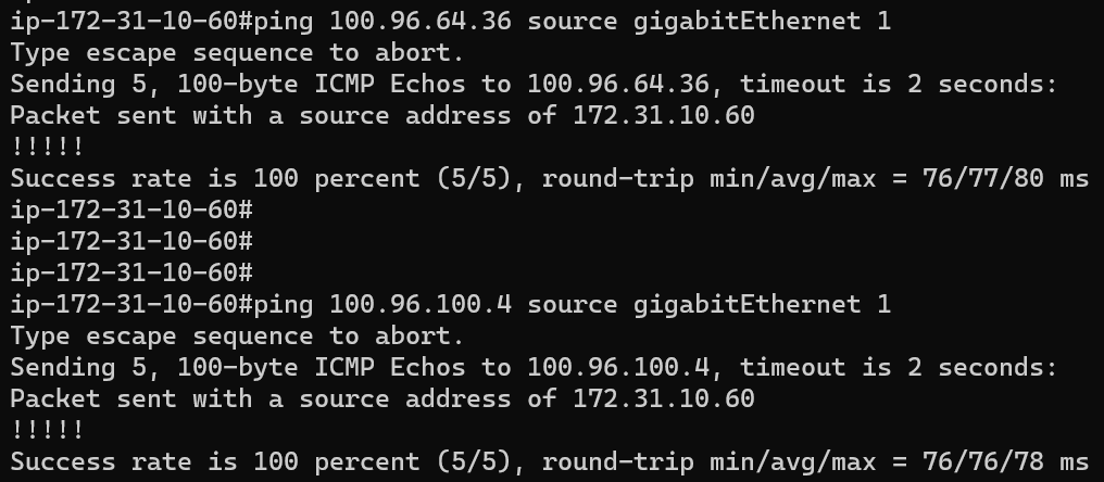
From the CSR 172.31.10.60 ping via GigabitEthernet 1
ping USEProdApp1Priv 10.100.64.36 using virtual IP: 100.96.64.36
ping USEShared1Pub 10.100.100.4 using virtual IP: 100.96.100.4
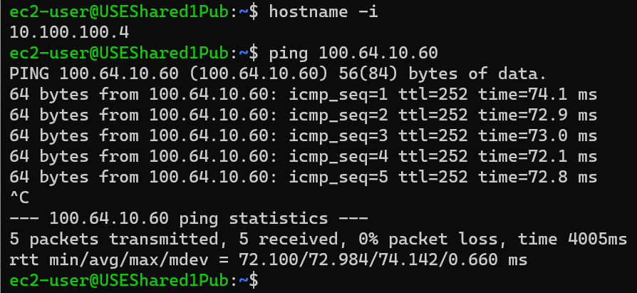
From USEShared1Pub 10.100.100.4
ping CSR 172.31.10.60 using virtual IP: 100.64.10.60
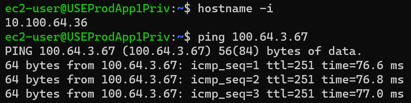
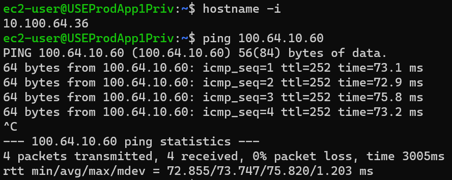
From USEProdApp1Priv 10.100.64.36
ping CSR 172.31.10.60 using virtual IP: 100.64.10.60
How about workloads on the same Default VPC as CSR?
We need to perform following:
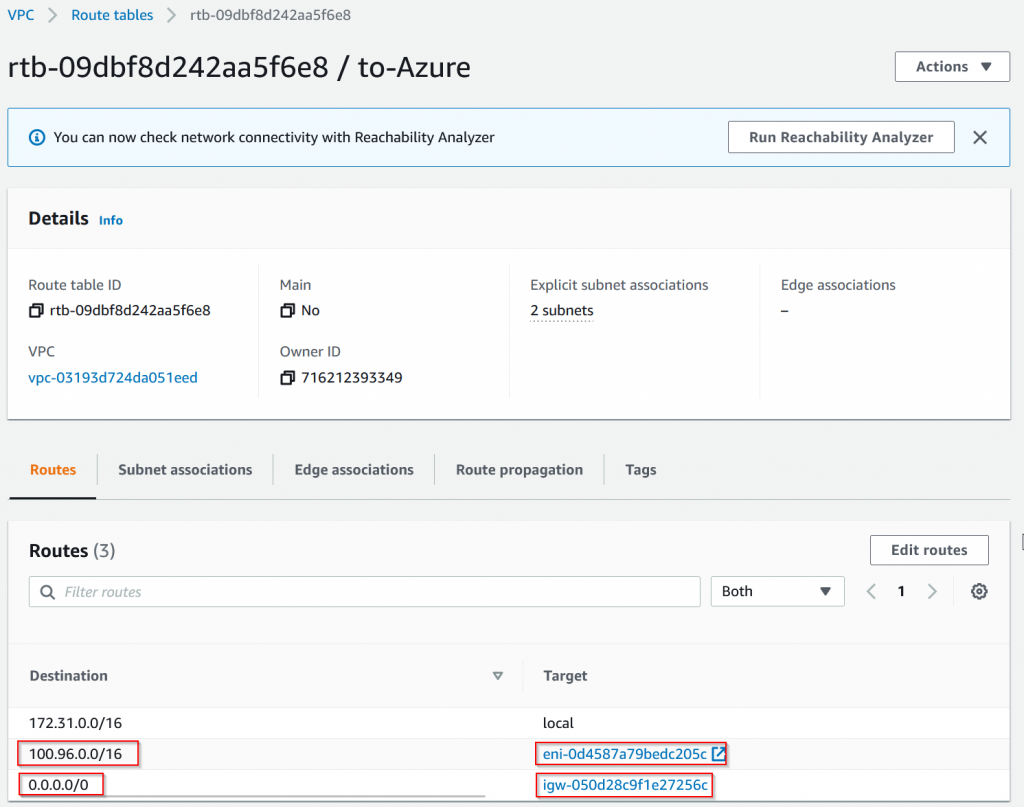
- Add route table on subnets to point to CSR 172.31.10.60 for CIDR range: 100.96.0.0/16. In my case since I’m deploying it to the same subnet as CSR, I needed 0/0 pointing to IGW as well.
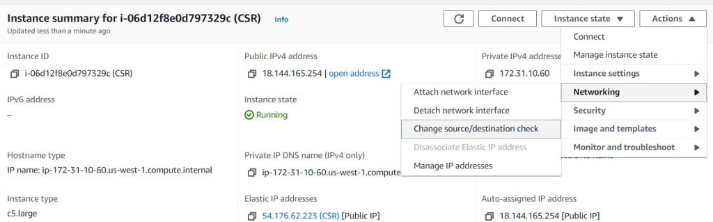
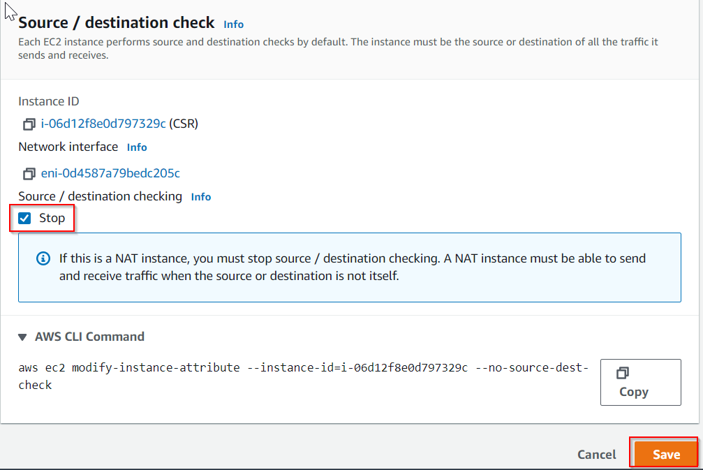
- Disable source/destination check on the CSR EC2 instance. (Azure equivalent Enable IP Forwarding)
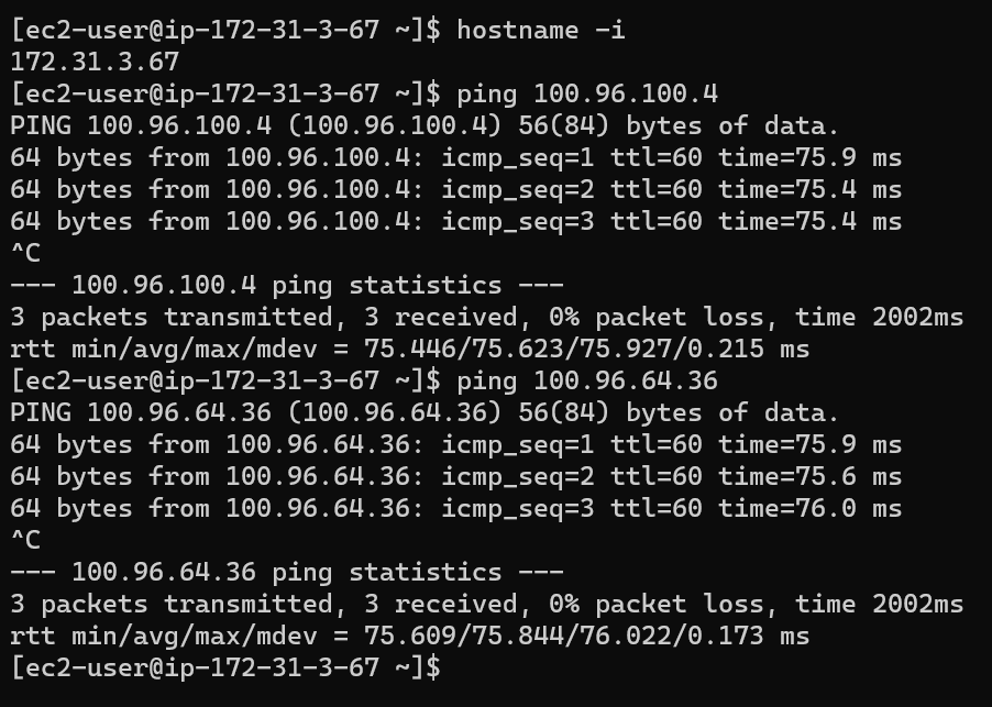
From test instance 172.31.3.67 in default VPC, it’s able to:
ping USEShared1Pub 10.100.100.4 using virtual IP: 100.96.100.4
ping USEProdApp1Priv 10.100.64.36 using virtual IP: 100.96.64.36
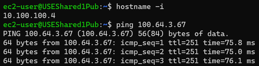
From USEShared1Pub 10.100.100.4
ping test instance 172.31.3.67 using virtual IP: 100.64.3.67
From USEProdApp1Priv 10.100.64.36
ping test instance 172.31.3.67 using virtual IP: 100.64.3.67